Tuning Guide
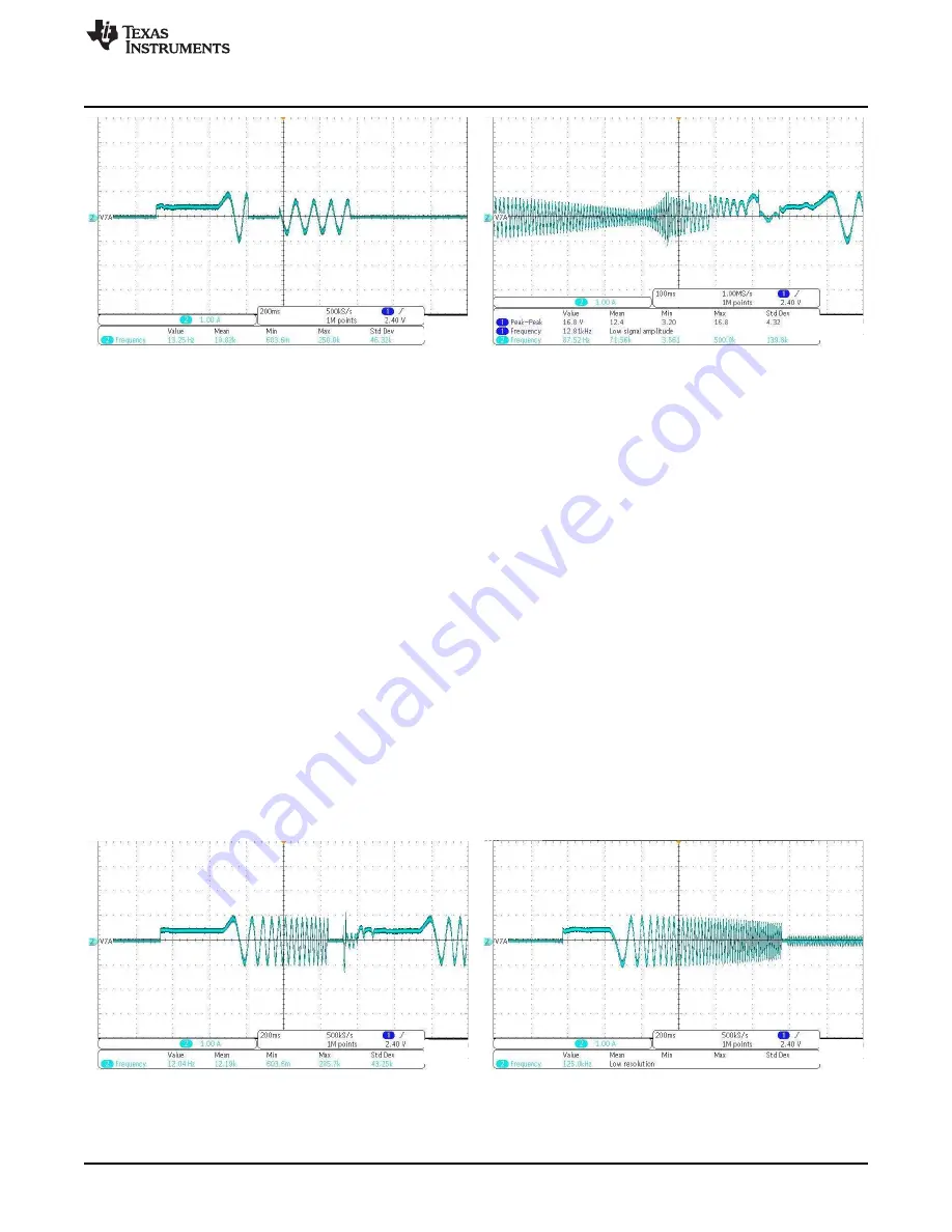
Figure 14. Open to Close Loop Threshold Too Low
Figure 15. Open to Close Loop Threshold Too High
6.1.3
PWM Duty Cycle Cutoff
PWM duty cycle cutoff decides the minimum operating duty cycle; this can be chosen to meet minimum
speed requirements. Refer to the DRV10963 datasheet for more information about the different minimum
duty cycles.
6.1.4
FG Frequency Divider
The FG pin provides an indication of the speed of the motor. There are two options, 1 or 1/2 toggles FG
once every 2 electrical cycles and 1 or 1/3, toggles FG once every 3 electrical cycles. This signal can be
used to get the motor speed feedback information. In order to see this relationship off of the FG pin on the
daughterboard, the device must be taken out of test mode by opening the jumper J1 on the motherboard,
using the POT R-17 for speed control, and the FGS pin must be driven low. For more information about
this, refer to the DRV10963 datasheet.
6.1.5
Software Current Limit
The software current limit function is only available in closed loop commutation mode. It works more like
an active current or better as torque limit, and does not cause overcurrent trip. This value can tune to get
a particular speed at a given motor loading condition. For example, increasing its value increases the
motor-applied torque and thus the speed, however, ensure that the value is not exuberantly high to
prevent motor heating. A lower value will prevent the motor from reaching a higher speed.
Start out at 0.125 A to make sure that your motor will spin and then slowly start to increase the current
limit until it fails, then use the current limit right before.
Figure 16. Current Limit Too High
Figure 17. Current Limit Very Small
15
SLAU643 – July 2015
DRV10963 Evaluation Module
Copyright © 2015, Texas Instruments Incorporated


