


January 2020
Part No. 1268514GT
Z
®
-33/18
4-3
Section 4 Fault Codes
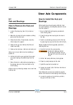
1 Turn the key switch to platform control.
2 Pull out the red Emergency Stop button to the
on position at both the ground and platform
controls.
3 Open the ground controls side turntable cover.
4 Locate the turntable control module (TCON)
underneath the ground control box.
5 Visually inspect the flashing green and red
LEDs on the controller.
The red LED indicates the source of the error and
the green LED indicates the error type.
6 Determine the error source
: The flashing red
LED, when combined with short or long pauses
between the flash, tells the service technician
the specific source of the error. Error source
code 32, for example, would appear as three
quick red flashes followed by a short pause of
almost two seconds, then two more quick red
flashes. Error source code 33 would appear
as three quick red flashes followed by a short
pause, then three more quick red flashes
followed by a long pause.
7 Determine the error type
: The flashing green
LED, when combined with short or long pauses
between the flash, tells the service technician
the specific error type. Error type code 12, for
example, would appear as one quick green
flash followed by a short pause of almost two
seconds, then two more quick green flashes
followed by a long pause. Error type code 15
would appear as one quick green flash followed
by a short pause, then five more quick green
flashes followed by a long pause.
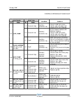
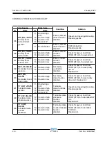
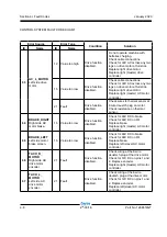
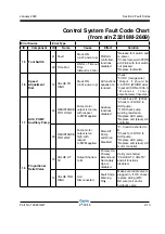
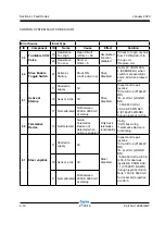
FAULT CODES
8 Use the fault code table on the following
pages to aid in troubleshooting the machine by
pinpointing the area or component affected.
Only control system fault codes can be retrieved
from TCON. Motor controller fault codes can only
be retrieved by following the procedure using the
platform controls.
See How to Retrieve Control
System Fault Codes from the Platform Controls
.
a green LED
b red LED
c turntable control module (TCON)
b
a
c
Содержание Genie Z-33/18
Страница 6: ...vi Z 33 18 Part No 1268514GT January 2020 This page intentionally left blank ...
Страница 12: ...xii Z 33 18 Part No 1268514GT January 2020 This page intentionally left blank ...
Страница 22: ...2 10 Z 33 18 Part No 1268514GT January 2020 Section 2 Specifications This page intentionally left blank ...
Страница 104: ...5 2 Z 33 18 Part No 1268514GT January 2020 Section 5 Schematics Electrical Symbols Legends ...
Страница 105: ...January 2020 Part No 1268514GT Z 33 18 5 3 Section 5 Schematics Hydraulic Symbols Legends ...
Страница 106: ...January 2020 Section 5 Schematics 5 4 5 5 Electrical Schematic ...
Страница 108: ...January 2020 Section 5 Schematics 5 7 Electrical Schematic ...
Страница 110: ...January 2020 Section 5 Schematics 5 9 Electrical Schematic ...
Страница 112: ...January 2020 Section 5 Schematics 5 11 Electrical Schematic ...
Страница 114: ...January 2020 Section 5 Schematics 5 13 Electrical Schematic ...
Страница 115: ...5 14 Z 33 18 Part No 1268514GT January 2020 Section 5 Schematics Electrical Schematic from S N Z3318M 2669 ...
Страница 116: ...5 15 Z 33 18 Part No 1268514GT January 2020 Section 5 Schematics Electrical Schematic from S N Z3318M 2669 ...
Страница 117: ...5 16 Z 33 18 Part No 1268514GT January 2020 Section 5 Schematics Hydraulic Schematic ...