3-32
Z
®
-33/18
Part No. 1268514GT
January 2020
Section 3 • Repair Procedures
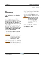
Calibration of the function pump is essential to
good machine performance and service life.
Continued use of an uncalibrated or improperly
calibrated function pump could result in reduced
machine performance. The function pump must be
calibrated before machine functions are calibrated
or before adjusting boom function speeds.
This procedure must be performed with the rotary
speed controller turned to the full clockwise
position.
1 Calibrate the proportional relief valve. See 6-2,
How to Calibrate the Proportional Relief Valve
.
2 Turn the key switch to platform control.
3 Pull out the red Emergency Stop buttons to the
on position at both the ground and platform
controls.
4 Do not press down the foot switch.
5 Move and hold the drive enable toggle switch in
the right direction while holding the steer rocker
switch in the right direction.
6 When the display leaves
SYSTEM READY
mode, release the drive enable toggle switch
and the steer rocker switch.
Result: The display will show
FAULTS
.
7 Momentarily activate the steer rocker switch in
the right direction until
SETTINGS
is shown on
the display.
8 Momentarily activate the drive enable toggle
switch in the right direction to enter the
SETTINGS
menu.
Result: The display will show
VALVE AND
PUMP SETTINGS
.
9 Momentarily activate the drive enable toggle
switch in the right direction to enter the
VALVE
AND PUMP SETTINGS
menu.
Result: The display will show
THRESHOLD
CURRENT
.
10 Momentarily activate the steer rocker switch in
the right direction until START PUMP GPM is
shown on the display.
11 Momentarily activate the drive enable toggle
switch in the right direction to begin pump
calibration.
12 Press down on the foot switch. Move and hold
the primary boom rocker switch in the extend
direction until the boom is fully extended and
an audible alarm has sounded.
Result: The alarm sounds. Continue to step 13.
Result: The alarm does not sound. Fully retract
the primary boom and repeat steps 11 and 12.
To exit programming mode:
13 Move and hold the drive enable toggle in the
left position until the display returns to
SYSTEM
READY
mode.
HYDRAULIC PUMPS
Содержание Genie Z-33/18
Страница 6: ...vi Z 33 18 Part No 1268514GT January 2020 This page intentionally left blank ...
Страница 12: ...xii Z 33 18 Part No 1268514GT January 2020 This page intentionally left blank ...
Страница 22: ...2 10 Z 33 18 Part No 1268514GT January 2020 Section 2 Specifications This page intentionally left blank ...
Страница 104: ...5 2 Z 33 18 Part No 1268514GT January 2020 Section 5 Schematics Electrical Symbols Legends ...
Страница 105: ...January 2020 Part No 1268514GT Z 33 18 5 3 Section 5 Schematics Hydraulic Symbols Legends ...
Страница 106: ...January 2020 Section 5 Schematics 5 4 5 5 Electrical Schematic ...
Страница 108: ...January 2020 Section 5 Schematics 5 7 Electrical Schematic ...
Страница 110: ...January 2020 Section 5 Schematics 5 9 Electrical Schematic ...
Страница 112: ...January 2020 Section 5 Schematics 5 11 Electrical Schematic ...
Страница 114: ...January 2020 Section 5 Schematics 5 13 Electrical Schematic ...
Страница 115: ...5 14 Z 33 18 Part No 1268514GT January 2020 Section 5 Schematics Electrical Schematic from S N Z3318M 2669 ...
Страница 116: ...5 15 Z 33 18 Part No 1268514GT January 2020 Section 5 Schematics Electrical Schematic from S N Z3318M 2669 ...
Страница 117: ...5 16 Z 33 18 Part No 1268514GT January 2020 Section 5 Schematics Hydraulic Schematic ...


