2-8
Z
®
-33/18
Part No. 1268514GT
January 2020
Section 2 • Specifications
SPECIFICATIONS
Torque Procedure
Seal-Lok
TM
fittings
1 Replace the O-ring. The O-ring must be
replaced anytime the seal has been broken.
The O-ring cannot be re-used if the fitting or
hose end has been tightened beyond finger
tight.
Note: The O-rings used in the Parker Seal Lok™
fittings and hose ends are custom-size O-rings.
They are not standard SAE size O-rings. They are
available in the O-ring field service kit (Genie part
number 49612).
2 Lubricate the O-ring before installation.
3 Be sure that the face seal O-ring is seated and
retained properly.
4 Position the tube and nut squarely on the face
seal end of the fitting and tighten the nut finger
tight.
5 Tighten the nut or fitting to the appropriate
torque per given size as shown in the table.
6 Operate all machine functions and inspect the
hoses and fittings and related components to
confirm that there are no leaks.
JIC 37° fittings
1 Align the tube flare (hex nut) against the nose
of the fitting body (body hex fitting) and tighten
the hex nut to the body hex fitting to hand-tight,
approximately 30 in-lbs / 3.4 Nm.
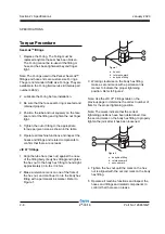
2 Make a reference mark on one of the flats of
the hex nut, and continue it on to the body hex
fitting with a permanent ink marker. Refer to
Figure 1.
3 Working clockwise on the body hex fitting,
make a second mark with a permanent ink
marker to indicate the proper tightening
position. Refer to Figure 2.
Note: Use the JIC 37° Fittings table on the
previous page to determine the correct number of
flats for the proper tightening position.
Note: The marks indicate that the correct
tightening positions have been determined. Use
the second mark on the body hex fitting to properly
tighten the joint after it has been loosened.
4 Tighten the hex nut until the mark on the hex
nut is aligned with the second mark on the body
hex fitting.
5 Operate all machine functions and inspect the
hoses and fittings and related components to
confirm that there are no leaks.
a
b
c
a
b
c
b
Figure 1
a hex nut
b reference mark
c
body hex fitting
Figure 2
a body hex fitting
b reference mark
c
second mark
Содержание Genie Z-33/18
Страница 6: ...vi Z 33 18 Part No 1268514GT January 2020 This page intentionally left blank ...
Страница 12: ...xii Z 33 18 Part No 1268514GT January 2020 This page intentionally left blank ...
Страница 22: ...2 10 Z 33 18 Part No 1268514GT January 2020 Section 2 Specifications This page intentionally left blank ...
Страница 104: ...5 2 Z 33 18 Part No 1268514GT January 2020 Section 5 Schematics Electrical Symbols Legends ...
Страница 105: ...January 2020 Part No 1268514GT Z 33 18 5 3 Section 5 Schematics Hydraulic Symbols Legends ...
Страница 106: ...January 2020 Section 5 Schematics 5 4 5 5 Electrical Schematic ...
Страница 108: ...January 2020 Section 5 Schematics 5 7 Electrical Schematic ...
Страница 110: ...January 2020 Section 5 Schematics 5 9 Electrical Schematic ...
Страница 112: ...January 2020 Section 5 Schematics 5 11 Electrical Schematic ...
Страница 114: ...January 2020 Section 5 Schematics 5 13 Electrical Schematic ...
Страница 115: ...5 14 Z 33 18 Part No 1268514GT January 2020 Section 5 Schematics Electrical Schematic from S N Z3318M 2669 ...
Страница 116: ...5 15 Z 33 18 Part No 1268514GT January 2020 Section 5 Schematics Electrical Schematic from S N Z3318M 2669 ...
Страница 117: ...5 16 Z 33 18 Part No 1268514GT January 2020 Section 5 Schematics Hydraulic Schematic ...


