


3-44
Z
®
-33/18
Part No. 1268514GT
January 2020
Section 3 • Repair Procedures
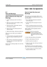
10 Install a new cotter pin. Bend the cotter pin to
lock it in place.
Note: Always use a new cotter pin when installing
a castle nut.
11 Install the dust cap, then the tire and wheel
assembly.
12 Lower the machine and remove the blocks.
13 Torque the wheel lug nuts to specification.
Refer to Section 2,
Specifications
. 9-1.
The steer angle sensor, installed on the steer yoke
pivot pin, is monitored by the control system to
determine steer angle. The control system uses
the steer angle input, along with pre-programmed
parameters, to vary the speed of each drive
motor while steering to minimize tire scrub and to
help minimize turning radius. Drive speed is also
reduced proportionately depending on the steer
angle to minimize lateral platform acceleration.
1 Adjust the steer tires so they are in a straight
driving position.
2 Turn the key switch to the off position.
3 Push in the red Emergency Stop buttons to
the off position at both the ground and platform
controls.
4 Remove the drive chassis cover at the steer
end of the machine.
5 Remove the cable clamp securing the steer
sensor cable to the chassis.
6 Tag and disconnect the steer sensor harness
from the main harness.
7 Remove the steer sensor cover retaining
fasteners. Remove the steer sensor assembly
from the machine.
Inspect the sensor activator pin to make sure it is
not broken or twisted.
If the sensor activator pin needs to be replaced,
note the mounting orientation to be sure the new
one is installed correctly.
STEER AXLE COMPONENTS
Содержание Genie Z-33/18
Страница 6: ...vi Z 33 18 Part No 1268514GT January 2020 This page intentionally left blank ...
Страница 12: ...xii Z 33 18 Part No 1268514GT January 2020 This page intentionally left blank ...
Страница 22: ...2 10 Z 33 18 Part No 1268514GT January 2020 Section 2 Specifications This page intentionally left blank ...
Страница 104: ...5 2 Z 33 18 Part No 1268514GT January 2020 Section 5 Schematics Electrical Symbols Legends ...
Страница 105: ...January 2020 Part No 1268514GT Z 33 18 5 3 Section 5 Schematics Hydraulic Symbols Legends ...
Страница 106: ...January 2020 Section 5 Schematics 5 4 5 5 Electrical Schematic ...
Страница 108: ...January 2020 Section 5 Schematics 5 7 Electrical Schematic ...
Страница 110: ...January 2020 Section 5 Schematics 5 9 Electrical Schematic ...
Страница 112: ...January 2020 Section 5 Schematics 5 11 Electrical Schematic ...
Страница 114: ...January 2020 Section 5 Schematics 5 13 Electrical Schematic ...
Страница 115: ...5 14 Z 33 18 Part No 1268514GT January 2020 Section 5 Schematics Electrical Schematic from S N Z3318M 2669 ...
Страница 116: ...5 15 Z 33 18 Part No 1268514GT January 2020 Section 5 Schematics Electrical Schematic from S N Z3318M 2669 ...
Страница 117: ...5 16 Z 33 18 Part No 1268514GT January 2020 Section 5 Schematics Hydraulic Schematic ...