4-30
Z
®
-33/18
Part No. 1268514GT
January 2020
Section 4 • Fault Codes
Drive Motor Thermal Sensor
Te m pe ra ture
Re sista nce
°F / °C
Ohm
-40 / -40
355
-22 / -30
386
-4 / -20
419
14 / -10
455
32 / 0
493
50 / 10
533
68 /20
576
77 / 25
598
86 / 30
621
104 / 40
668
122 / 50
718
140 / 60
769
158 / 70
824
176 / 80
880
194 / 90
939
212 / 100
1000
230 / 110
1063
248 / 120
1129
266 / 130
1197
284 / 140
1268
302 / 150
1340
320 / 160
1415
338 / 170
1493
347 / 180
1572
374 / 190
1654
392 / 200
1739
410 / 210
1825
428 / 220
1914
446 / 230
2006
464 / 240
2099
482 / 250
2195
500 / 260
2293
518 / 270
2392
536 / 280
2490
554 / 290
2584
572 / 300
2668
The thermal sensor is monitored by the motor
controllers to maintain optimum performance and
as a thermal shutdown protection device.
Normal safe operating range is between -40°F /
-40°C and 131°F / 55°C at an 85% duty cycle.
Thermal faults will occur when the temperature
exceeds its threshold of 302°F / 150°C. Then drive
speeds will be reduced by 50%.
Thermal shut down occurs at 392°F / 200°C.
1 Disconnect the battery packs from the machine.
WARNING
Electrocution/burn hazard.
Contact with electrically charged
circuits could result in death or
serious injury.
Remove all rings, watches and
other jewelry.
2 Remove the chassis cover fasteners from the
non-steer end of the chassis. Remove the
cover.
3 Tag and disconnect the six pin Deutsch
electrical connector for the speed and
temperature sensor at the drive motor.
4 Measure the drive motor case temperature
using a thermometer.
5 Measure the resistance between pins 5 and 6
on the Deutsch connector going into the motor
housing. Compare value to chart on right.
Содержание Genie Z-33/18
Страница 6: ...vi Z 33 18 Part No 1268514GT January 2020 This page intentionally left blank ...
Страница 12: ...xii Z 33 18 Part No 1268514GT January 2020 This page intentionally left blank ...
Страница 22: ...2 10 Z 33 18 Part No 1268514GT January 2020 Section 2 Specifications This page intentionally left blank ...
Страница 104: ...5 2 Z 33 18 Part No 1268514GT January 2020 Section 5 Schematics Electrical Symbols Legends ...
Страница 105: ...January 2020 Part No 1268514GT Z 33 18 5 3 Section 5 Schematics Hydraulic Symbols Legends ...
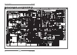
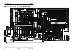
Страница 106: ...January 2020 Section 5 Schematics 5 4 5 5 Electrical Schematic ...
Страница 108: ...January 2020 Section 5 Schematics 5 7 Electrical Schematic ...
Страница 110: ...January 2020 Section 5 Schematics 5 9 Electrical Schematic ...
Страница 112: ...January 2020 Section 5 Schematics 5 11 Electrical Schematic ...
Страница 114: ...January 2020 Section 5 Schematics 5 13 Electrical Schematic ...
Страница 115: ...5 14 Z 33 18 Part No 1268514GT January 2020 Section 5 Schematics Electrical Schematic from S N Z3318M 2669 ...
Страница 116: ...5 15 Z 33 18 Part No 1268514GT January 2020 Section 5 Schematics Electrical Schematic from S N Z3318M 2669 ...
Страница 117: ...5 16 Z 33 18 Part No 1268514GT January 2020 Section 5 Schematics Hydraulic Schematic ...

