background image

Operator’s Manual Simple AFG Application


84 


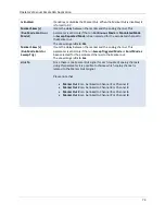
Once all the instruments have been connected, turn them on and launch the Simple AFG Application in 
all the instruments. 

Please note


that


Turn off the instruments before connecting or disconnecting the Sync Cables  


The external clock source and external trigger input are available in Master device only 

The following steps describe the operations that you should perform to set up a multi-Instrument 
system and start the generation of two devices. 


1.


On Master and Slave units, launch the Simple AFG Application. 


2.


On the Master unit (the one with the Sync OUT port connected) will appear a new Master 
Multi-instrument bar: 


3.


On the Slave unit (the one with the Sync IN port connected) will appear a new Slave Multi- 
instrument bar: 
 

Содержание T3AWG325X

Страница 1: ...Operator s Manual T3AWG3K Series Simple AFG Rev 2 0 3 ...

Страница 2: ...L CONSIDERATIONS 8 PRODUCT END OF LIFE HANDLING 8 EQUIPMENT RECYCLING 8 PREFACE 9 PACKAGECONTENTS 9 RECOMMENDED ACCESSORIES T3AWG3352 3252 9 RECOMMENDED ACCESSORIES T3AWG3354 3254 9 RECOMMENDED ACCESSORIES T3AWG3358 3258 10 MECHANICAL CHARACTERISTICS 10 KEY FEATURES 11 INSTALLING YOUR INSTRUMENT 11 OPERATING REQUIREMENTS 11 ENVIRONMENTAL REQUIREMENTS 12 POWER SUPPLY REQUIREMENTS 12 CLEANING 13 CAL...

Страница 3: ...s T3AWG3358 3258 only 27 INTRODUCTION 28 SIMPLE AFG SOFTWARE 28 SIMPLE AFG TOUCH UI 28 USER INTERFACE DESCRIPTION 29 Waveform Parameters Area 30 Graph Area 32 Zoom graph 33 Channel Information 38 Command Bar Area 38 INPUT OUTPUT CHANNELS 41 ANALOG OUTPUT CHANNEL 41 Main Parameters 41 AUXILIARY CHANNELS 46 Marker Out 47 Trigger In 47 Reference Clock Input Connector 48 External Modulation Input Conn...

Страница 4: ...RIGGER SETTINGS TAB 71 MARKER SETTINGS 72 MAIN COMMAND BUTTON DESCRIPTION 74 SAVE AS 74 EXPORT CONFIGURATION 74 LOAD FROM 74 REMOTE CONTROL 75 REMOTE DESKTOP CONNECTION 76 WAVEFORM LIST 77 HOW TO IMPORT A WAVEFORM FROM A FILE 78 How to export a waveform to a file 78 How to promote a waveform to a Predefined 78 How to edit a Waveform 79 How to create a new Waveform 79 CHANNEL COUPLING 80 CALIBRATIO...

Страница 5: ...product ensure that the product is properly grounded Observe All Terminal Ratings To avoid fire or shock hazard observe all ratings and markings on the product Consult the product manual for further ratings information before making connections to the product Power Disconnect The power cord provides Mains disconnect Do Not Operate Without Covers Do not operate this product with covers or panels re...

Страница 6: ...mation or documents in order to protect against personal injury or damage to the instrument This symbol warns of a potential risk of shock hazard This symbol is used to denote the measurement ground connection This symbol is used to denote a frame or chassis connection This symbol is used to denote a safety ground connection On Supply This is the DC power connect disconnect switch at the back of t...

Страница 7: ...dicates a potential hazard It calls attention to a procedure practice or condition which if not followed could possibly cause bodily injury or death If a WARNING is indicated do not proceed until its conditions are fully understood and met CAT I Installation Overvoltage Category rating per EN 61010 1 safety standard and is applicable for the instrument front panel measuring terminals CAT I rated t...

Страница 8: ...ful to the environment or human health if improperly handled at the product s end of life In order to avoid release of such substances into the environment and to reduce the use of natural resources we encourage you to recycle this product in an appropriate system that will ensure that most of the materials are reused or recycled appropriately The symbol shown to the left indicates that this produ...

Страница 9: ...tecture provides the possibility to easily generate predefined waveforms and modulated signals or to load an arbitrary waveform from a user defined file Package Contents The standard T3AWG 3K Series package includes the following T3AWG325X or T3AWG335X Arbitrary Waveform Generator equipment Power Cord Performance Calibration Certificate Quick Start Guide CE certificate Recommended Accessories T3AW...

Страница 10: ...pter cable T3AWG3 8DIG MSCAB Digital output LVDS cable T3AWG3 SYNC Synchronization cable for T3AWG3K 8CH not used with Simple AFG application Mechanical Characteristics Model T3AWG3352 T3AWG3252 Net Weight 6 5kg Net Weight with Package 7 kg Overall Dimensions Height 143 mm Width 362 mm Depth 258 mm Model T3AWG3354 T3AWG3254 Net Weight 10 kg Net Weight with Package 10 5 kg Overall Dimensions Height...

Страница 11: ...ce to create complex waveforms scenarios just in few screen touches Large 7 inch 1024x600 capacitive touch LCD Touchscreen or Keypad data entering Windows 10 operating system USB and LAN interfaces Compact case size with the possibility of rack mounting in 3U Installing your instrument Unpack the instrument and check that you received all items listed in the Package Content paragraph NOTE The inst...

Страница 12: ...rating 20 C to 60 C 4 F to 140 F Humidity Operating 5 to 80 relative humidity with a maximum wet bulk temperature of 29 C at or below 40 C non condensing Non operating 5 to 95 relative humidity with a maximum wet bulb temperature of 40 C at or below 60 C non condensing Altitude Operating 3 000 m 9 843 feet Non operating 12 000 m 39 370 feet Power supply requirements WARNING To reduce the risk of f...

Страница 13: ...ace of the arbitrary waveform generator do not use any abrasive or chemical cleaning agents Calibration The recommended calibration interval is one year Calibration should be performed by qualified personnel only Abnormal Conditions Operate the instrument only as intended by the manufacturer If you suspect the instrument s protection has been impaired disconnect the power cord and secure the instr...

Страница 14: ...the previous power off the instrument was working in AFG mode Alternatively push the AFG icon to launch the application from the desktop or push the Switch To button to switch in AFG mode from another application Power Off Close the application in use Press the front panel power button to power off the instrument Protect Your Instrument from Misuse Check Input and Output Connectors When connecting...

Страница 15: ...pplication 15 CAUTION Do not short output pins or apply external voltages to Output connectors The instrument may be damaged CAUTION Do not apply excessive inputs over 15 Vpk to Trigger Input connector The instrument may be damaged ...

Страница 16: ...om in the support area Install Simple AFG Application If your instrument has already installed another version of the Simple AFG application DO NOT uninstall it otherwise you will lose all the configurations and projects 1 Download the Simple AFG setup package from Teledyne LeCroy website and decompress it to instrument s local disk 2 Right click on the Add AppDevPackage ps1 file and select Run wi...

Страница 17: ...Operator s Manual Simple AFG Application 17 3 When the application has been installed press the Enter button to continue ...

Страница 18: ...Simple AFG Application 18 Instrument Overview Front Panel T3AWG3352 3252 7 Capacitive Touch Screen Soft Keyboard and Rotary Knob Numeric Keypad Power on off button Single ended analog outputs Trigger In and Marker Output ...

Страница 19: ...r s Manual Simple AFG Application 19 Front Panel T3AWG3354 3254 7 Capacitive Touch Screen Soft Keyboard and Rotary Knob Single ended analog outputs Trigger In and Marker Outputs Numeric Keypad 2 USB 3 0 ports ...

Страница 20: ...Marker Out is a digital output channel that generates a pulse related to the analog waveform Its impedance is 50 Ohm and the output voltage amplitude ranges from 1 V to 2 5 V into 50 Ohm load The Marker Out generates a digital pulse synchronous with the waveform depending on the Run Mode To set the Marker Out parameters refer to the Marker Out Settings The connector type is a standard BNC 7 Capaci...

Страница 21: ... Channel Out 8 Model Marker Out Connectors T3AWG3352 3252 1 BNC on the Front Panel T3AWG3354 3254 2 BNCs on the Front Panel T3AWG3358 3258 4 BNCs on the Front Panel Trigger In The Trigger In Trigger In connector on the front panel allows to control the generation by an external signal source It has a selectable impedance of 1 kOhm or 50 Ohm In Continuous mode the Trigger In doesn t have any effect...

Страница 22: ...he virtual numeric pad A useful central knob is available for fine tuning and adjustments during the on the fly set up operation The rotary knob will change the value in continuous analog fashion The push button rotary knob lets you to change the value increment between Coarse and Fine adjustment The key will move the selected digit to the right and the key will move the selected digit to right Yo...

Страница 23: ...quency of the waveform AWG AFG Use this button to switch between AFG mode and AWG operating mode OFFSET V LOW Use this button to set the low voltage level or the offset of the waveform PHASE DELAY N A SETTINGS Use this button to open the Settings page CHANNEL SEL Use this button to change the output selection in the user interface ALL OFF Use this button to turn off all the outputs DEFAULT Use thi...

Страница 24: ...s G n it will be GHz if you press T p nothing will happen because that range is not available for the selected parameter If both the two unit of measure of a Unit Measure Range button are available for the selected parameter i e Mega and Micro if you press the range button M u the range will switch accordingly between Mega and Micro Rear Panel T3AWG3352 T3AWG3252 The callouts on this image gives t...

Страница 25: ...tors Rear Panel T3AWG3358 T3AWG3258 Digital Output Connector 1 Ref Clk In 5 to 100 MHz 1 10_MHz Ref Clock Output 1 External Modulation Input 4 USB 3 0 ports 2 Gigabit LAN port 3 Audio IN OUT 1 HDMI 1 4 port 1 VGA port 1 DVI D port 1 Display 1 2 port 1 PS 2 Mouse Keyboard ports 1 COM port 2 Digital Output Connector Pod A Pod B 2 Slots for Removable SSD ...

Страница 26: ... 100 MHz 1 10_MHz Ref Clock Output 1 External Modulation Input 1 Sync IN Sync Out Connectors 4 USB 3 0 ports 2 Gigabit LAN port 3 Audio IN OUT 1 HDMI 1 4 port 1 VGA port 1 DVI D port 1 Display 1 2 port 1 PS 2 Mouse Keyboard ports 1 COM port 2 Slots for Removable SSD 4 Digital Output Connectors Pod A Pod B Pod C Pod D ...

Страница 27: ...ling clock frequency This feature allows to synchronize the generator with an external clock The connector type is a SMA Reference Clock Output Connector This connector outputs the internal 10MHz reference clock used to synthesize the DAC sampling clock If the clock source is internal it produces a signal at 10 MHz if the source is external it is disabled The connector type is a SMA Digital Output...

Страница 28: ...uch user interface based on a Microsoft Windows 10 platform You can control instrument operations using one or all of the following entering methods Touch Screen and Front panel soft key controls Keyboard and mouse Simple AFG Touch UI Simple AFG UI is designed for touch to drive simplicity in operating with an Arbitrary Waveform Generator by using the today s modern technique used on Tablet or sma...

Страница 29: ...fine the Modulation Sweep or Burst parameters depending on the selected Run Mode or to access to others Channel Parameters Graph Area it shows a qualitative graphical representation of the generated waveform Channel Information it summarizes the channel settings Command Bar in this bar there are elements to control the instrument operations to modify the instrument settings and to manipulate wavef...

Страница 30: ...d in the relative chapter If the Run Mode option selected is different from Continuous will compare another tab right side Carrier Tab it is possible to define the parameters that describe the Modulation Sweep and Burst This tab changes title name and functionality depending on the selected Run Mode For example if the Run Mode is Sweep the Secondary tab will take the title name Sweep and the tab p...

Страница 31: ...erator s Manual Simple AFG Application 31 You can touch the parameter area to open the Virtual numeric keypad edit the parameter value and its measure unit Below there is a description of the keypad items ...

Страница 32: ...n increment or decrement the selected parameter using the UP DOWN arrows button or rotating knob on the front panel When Fine is selected the increment is of 1 unit at the current cursor position When Coarse is pressed the Delta increment is displayed in the parameter area and the parameter value changes in steps of the selected increment You can keep pressed the knob and rotate it on the right or...

Страница 33: ... only the channels that you want tapping on coloured buttons under the graph Checking View Grid you can view further horizontal and vertical line with additional values of amplitude Zoom graph Tapping on the highlighted button below you can open another panel with more functions that expands the functionality of the graph In particular this new panel give you the possibility to Zoom into area of t...

Страница 34: ...mes Scale you can zoom into area using two fingers as multitouch to zoom in and out one finger to translate window zoom left or right otherwise you can select a rectangle area if the correct button is enabled Every time that you Zoom In will be add to a stack the previous value of Zoom and will be show two buttons Reset and Back in the command bar these buttons permit you to come back the previous...

Страница 35: ...o that sample at same way if you are in Times Scale but you must insert a time value The range of the Samples Scale is 0 to 16384 while the Time Range depends of the values set on the Channel Data 2 ALL CH enable or disable the View All Channels You can decide to View only the channels that you want tapping on coloured buttons under the graph 3 Times Scale if enabled the Times Scale is visible oth...

Страница 36: ...amplitude and Samples Times 5 Zoom Rect Area if enabled the multitouch and the translation left right will be disabled you can holding down and then release to select an area to Zoom 6 Cursor enable this button if you want to see a cursor on the graph that visualize the values Sample Time and Amplitude of the waveforms in the position set ...

Страница 37: ...Operator s Manual Simple AFG Application 37 7 Info Buttons tap to open a panel where they are indicated a lite description of the buttons just listed ...

Страница 38: ...ow a detailed description of this bar is provided Command Bar Buttons Description Running Stopped Button Use this button to set the instrument in Running state or Ready to receive a Trigger or in the Stopped state If the button is green the instrument is running while if it is grey the instrument is stopped Bushing the button will change the instrument state Trigger Button Use this button to send ...

Страница 39: ...ore information please refer to the relative section Note this button is in the More menu on the four eight channel model Default Use this button to restore the default value of all parameters of the instrument Note this button is in the More menu on the four eight channel model Numeric Keyboard Button Use this button to enable or disable the virtual numeric keyboard Note this button is in the Mor...

Страница 40: ...arameters from Voltage High V and Voltage Low V to Amplitude Vpp Offset V or between Symbol Duration s to Symbol Rate S s Change Application Use this button to switch from AFG to TrueArb or SPG application About Button Use this button to check the credits the software and firmware release number and the instrument serial number Help Button Use this button to open the User Manual Calibration button...

Страница 41: ...gnals are common input sources for every instrument channels Analog Output Channel The term Output Channel as used in this user manual refers to the analog signal provided on the BNC output connector located on the front instrument panel For some parameters the Simple AFG application supports different input formats For example it is possible to specify the frequency of a waveform or alternatively...

Страница 42: ...ean Square Voltage it is the rms value of the waveform dBm it is the power transferred to the load expressed in dBmW this representation is available only for sine wave Its value takes into account the Load impedance parameter specified in Channel Settings Note The Vrms and the dBm values set in the textbox are referred only to the waveform amplitude They don t take into consideration the Offset o...

Страница 43: ...Operator s Manual Simple AFG Application 43 The amplitude and the offset can be represented in four different formats as listed before that can be selected by rotate the 3D cube as below ...

Страница 44: ...Operator s Manual Simple AFG Application 44 ...

Страница 45: ...e When you set the Noise amplitude please pay attention that Signal Noise does not exceed the amplitude of 12 Vpp HV option Internal Noise Use this control to enable or disable the noise added to the output signal Symmetry This parameter is defined only for the Ramp function It represents the percentage of the cycle in which the ramp function is rising Width s Duty Cycle It defines the duration of...

Страница 46: ...10 and the 90 of the pulse amplitude The 0 to 100 transitions will be longer than the set values anyway the graph represents the entered value as the 0 to 100 transition time Note Using the Pulse Waveform the following constraints must be met 𝑅𝑖𝑠𝑖𝑛𝑔 𝐸𝑑𝑔𝑒 𝐹𝑎𝑙𝑙𝑖𝑛𝑔 𝐸𝑑𝑔𝑒 𝑃𝑒𝑟𝑖𝑜𝑑 𝑊𝑖𝑑𝑡ℎ 𝑃𝑒𝑟𝑖𝑜𝑑 Auxiliary Channels ...

Страница 47: ...1 V to 2 5 V Marker out blue top synchronous with the analog signal red bottom Trigger In The TRIGGER IN Trigger In connector on the front panel allows to control the signal generation when a channel is in Burst Run Mode or in Sweep Run Mode Refer to the chapters about the Device Settings to know how to define the trigger parameters or the Run Mode In Continuous and Modulation Run Modes the Trigge...

Страница 48: ...clock signal Reference Clock Input Value Connector type 1 SMA on the Rear Panel Input impedance 50 Ohm AC coupled Input Frequency range 5 MHz to 100 MHz External Modulation Input Connector The T3AWG 3K series instrument can accept the modulating signal from an external source through the External Modulation Input SMA connectors located on the Rear Panel External Modulating Input Description Connec...

Страница 49: ...is external it is disabled The connector type is a SMA Reference Clock Input Value Connector 1 SMA on the Rear Panel Output impedance 50Ω AC coupled Digital Output connector Important Note this connector is not used by AFG application Sync In Sync Out Connectors T3AWG3358 T3AWG3258 only The purpose of those connectors is to connect and synchronize together multiple instruments up to 4 instruments ...

Страница 50: ...from a file or from remote Touching the Carrier Wave button a dropdown menu opens where it is possible to select the waveform that is used as carrier waveform List and parameters of predefined waveforms The following table shows the available waveforms the parameters that you can change for each one and the possible combination of run mode and waveforms The Continuous Run Mode has been omitted fro...

Страница 51: ... Phase Ramp Amplitude Offset Frequency Phase Symmetry Pulse Amplitude Offset Frequency Phase Duty Cycle Leading Edge Trailing Edge Double Pulse Common Offset Frequency Phase Pulse 1 Pulse 2 Amplitude1 2 Offset1 2 Leading Edge1 2 Trailing Edge1 2 Width1 2 Delay1 2 Note Delay2 is a delta delay relative to the end of the first pulse Sinc Amplitude Offset Frequency Phase ...

Страница 52: ...ep Burst Noise Noise level Amplitude Offset DC Level Offset Gaussian Amplitude Offset Frequency Phase Lorentz Amplitude Offset Frequency Phase Exponential Rise Amplitude Offset Frequency Phase Exponential Decrease Amplitude Offset Frequency Phase Haversine Amplitude Offset Frequency Phase ...

Страница 53: ...ription paragraph Note When Arbitrary waveform is selected the amplitude and offset of the original waveform are lost because the waveform in normalized Anyway the amplitude and offset of the normalized waveform can be modified as for any predefined waveforms Note In Stopped State the instrument stops at the Baseline Offset of the selected channel for all the waveforms except for Pulse Waveform St...

Страница 54: ...rectly on the secondary tab that takes the name of the selected Run Mode Note after enabling a channel and pressing the Running button see Command Tool Area section the generation of the corresponding waveform will start keeping the first sample of the waveform constant for about 200ns For example in the picture below is represented the initial part of the generation of a sine wave with 50 deg of ...

Страница 55: ...nual Simple AFG Application 55 Continuous In the Continuous mode when the Run Stop button is pressed the waveform is reproduced continuously until the Run Stop button is pressed again or Waveform Run Mode is changed ...

Страница 56: ...MHz Over 75MHz the Marker Out frequency is divided by an integer value as described in the following Marker out frequency Carrier frequency 1 when Carrier frequency 75MHz Marker out frequency Carrier frequency 2 when 75MHz Carrier frequency 150MHz Marker out frequency Carrier frequency 4 when 150MHz Carrier frequency 300MHz Marker out blue top synchronous with the analog signal red bottom Note for...

Страница 57: ...n the modulation type menu opens as shown in the picture below With the button Hide Profile you can view and hide the waveform modulation profile on the graph The modulation types are Amplitude Modulation AM Frequency Modulation FM Phase Modulation PM Frequency Shift Keying FSK Phase Shift Keying PSK Pulse Width Modulation PWM The PWM modulation is the only modulation supported by the Pulse wavefo...

Страница 58: ...ary it allows to load a Modulating Waveform from file By default the Arbitrary waveform is a cosine function As Carrier Arbitrary you can select the waveform by combo box Waveform List Marker Out behaviour in Modulation Run Mode If the modulating source is Internal the Marker Out generates a square wave synchronous with the modulating waveform The leading edge of this pulse is positioned at the be...

Страница 59: ...een 0 and 120 Frequency Modulation FM the frequency of the carrier waveform is modulated following the modulating shape it is available for all functions except for the Pulse Double Pulse DC level and Noise The parameter Deviation Hz defines the deviation of frequency with respect to the carrier frequency The Deviation is between 0 Hz and the maximum frequency that satisfies the following 2 relati...

Страница 60: ... of modulation is a 2 level PSK The carrier phase is shifted by the value of Hop Phase deg It is available for all functions except for the Pulse Double Pulse DC level and Noise The hop phase is between 0 and 360 deg Pulse Width Modulation PWM this modulation is available only for the Pulse waveform It modulates the width of the Pulse of the quantity defined in the Deviation parameter that defines...

Страница 61: ...ned The User Defined selection gives the possibility to load the sweep profile from a file The Sweep is available for all function except for Pulse Double Pulse Noise and DC level Sweep Mode Touching the Sweep Mode button a menu opens that gives the possibility to choose a sweep profile among the following Linear the frequency increases and decreases linearly ...

Страница 62: ...he Start Frequency Note the time parameters must meet the following conditions 𝑅𝑖𝑠𝑖𝑛𝑔 𝑇𝑖𝑚𝑒 𝐻𝑜𝑙𝑑𝑖𝑛𝑔 𝑇𝑖𝑚𝑒 𝐹𝑎𝑙𝑙𝑖𝑛𝑔 𝑇𝑖𝑚𝑒 2000 𝑠 Step Number N it selects the number of frequency steps of the Upstair Sweep mode Start Frequency Hz it selects the initial sweep frequency Stop Frequency Hz it selects the final sweep frequency Sweep Trigger Mode Repeat the instrument starts when the Run Stop button is presse...

Страница 63: ...Operator s Manual Simple AFG Application 63 Marker out blue top synchronous with the sweep red bottom ...

Страница 64: ...Trigger signal is at High Level depending on the selected Burst Type This Run Mode is available for all waveforms except the DC level Burst Mode The burst mode allows to define the behaviour of the instrument after the Trigger reception Touching the Mode button the following menu opens and it is possible to select the burst type ...

Страница 65: ...trument terminates the current burst sequence then it returns waiting for the next trigger In Gated mode if the source of trigger is external from connector BNC Trigger In a trigger condition is true when it crosses the selected Threshold with the selected Edge otherwise it s false when it crosses the selected Threshold with the opposite Edge the Both option for the Edge parameter is meaningless i...

Страница 66: ... true except for Exponential Rise Exponential Decrease and Arbitrary Carrier where the Wait Trigger On parameter is enabled In this case the user can set which voltage level will be generated between one burst and another the carrier s first or last sample Exponential Rise Carrier 1 Cycle Burst Mode Wait Trigger On First Sample Exponential Rise Carrier 1 Cycle Burst Mode Wait Trigger On Last Sampl...

Страница 67: ...ker s skew is 3us Es 1 in the following picture the gated mode operation is shown From top to bottom there are C3 blue trace is the Trigger signal source from the external Trigger In 1 connector C2 red trace is the generated signal C1 yellow trace is the marker out Burst Gated with Trigger from external Trigger In 1 Es 2 in the following picture the 1 Cycle Burst mode operation is shown A sine wav...

Страница 68: ... on the defined Load expressed in Ohm The impedance range is 1 Ohm to 1 MOhm Baseline Offset V Defines the DC offset value added to the output signal respect to the ground level The range is between 6 V to 6 V HV option on 50 Ohm load and it depends on the selected load impedance i e 12V to 12V into open load Polarity This control allows you to invert the polarity of the output signal relative to ...

Страница 69: ...re about the Baseline Offset The constraint Low Limit High Limit must be met This feature can be used to ensure the load is not damaged Note The Low Limit doesn t force setting voltages under the limit but during the generation the part of the waveform that exceeds the limit will be cut at the Low Limit Output Impedance Ohm Sets the output instrument impedance to low 5 Ohm or to 50 Ohm Settings bu...

Страница 70: ...k is synthesized using a 10Mhz reference clock generated internally If the external Reference Clock In REF CLK is selected the DAC sampling clock is synthesized using the clock provided externally to the Ref Clock In SMA connector on the rear pannel of the instrument In this case the Ref Clk Frequency control will appear and the user must specify the Reference Clock frequency Hz The frequency rang...

Страница 71: ...lly to the Trigger In BNC connector when it crosses the selected Threshold Note the Trigger buttons and the Trigger from remote command are always active independently from the selected Trigger Source Timer Interval s Set the timer count interval It has effect only when the selecting trigger Source is Timer The Interval range is from 13 4ns to 100s The edited value is automatically rounded to the ...

Страница 72: ...uments The T3AWG 3352 3252 model has one Marker Out Marker Out 1 The T3AWG 3354 3254 model has two Marker Out Marker Out 1 Marker Out 2 The T3AWG 3358 3258 model has four Marker Outs Marker Out 1 Marker Out 2 Marker Out 3 Marker Out 4 Each Marker Out has its own set of parameters It is possible to switch among these set of parameters by clicking on the Marker Out 1 the Marker Out 4 icons located i...

Страница 73: ...urst or Sweep Trig It sets the delay between the marker and the analog channel This parameter is valid only if the run Sweep Triggered Mode or Burst Mode is been selected for the associated channel to the Marker out The skew range is 0s to 3us Link To Since there is one Marker Out signal for each couple of analog channels using this parameter it is possible to choose which analog channel is relate...

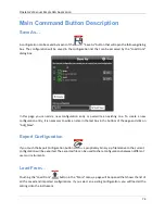
Страница 74: ...nfiguration entry it is necessary to write a name in the text box in the bottom of the page and click on Add_New Export Configuration If you touch the Export Configuration button a proprietary binary zip file relative to the current configuration will be exported The exported file can be used to share configurations between different users or instruments Load From Touching the Load From button in ...

Страница 75: ...nt machine or from a different user The imported configuration will be inserted in the Load From list Remote Control The Remote button located in the Command Bar opens the page of the SCPI server In that page there is the list of all the commands received by the SCPI server and its replies If the text of the command is displayed in green it means that the command is correct and it has been accepte...

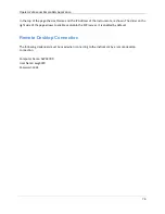
Страница 76: ...trument are shown The slider on the right side of the page allows to enable or disable the SCPI server It is enabled by default Remote Desktop Connection The following credentials must be used when connecting to the instrument by a remote desktop connection Computer Name AWG3000 User Name awg3000 Password 1234 ...

Страница 77: ...orms The Predefined Waveforms are the ones in red color on the list the imported waveforms are the ones in gray Please note that You can create your own set of Predefined Waveform by promoting waveforms in the list to Predefined ones You can delete a Predefined waveform with the exception of SINE and DC waveforms It is possible to restore the Factory Predefined waveforms by pressing the button All...

Страница 78: ... Description fields will be automatically filled with default values The imported waveform is normalized 3 Press OK to confirm or Close to cancel the operation How to export a waveform to a file Select a waveform on the waveform list Press the button The exported waveform will be stored in a proprietary binary zip file format that can be shared with other instruments running the same application Y...

Страница 79: ...o Predefined How to edit a Waveform Prerequisites Waveform Editor software installed Select a waveform on the waveform list Press the button to launch the Waveform Editor Please refer to the Waveform Editor user manual for a complete explanation about editing and creating waveforms How to create a new Waveform Prerequisites Waveform Editor software installed Press the button in the More menu to la...

Страница 80: ...channels of the instrument In Coupled mode the user can choose which Channel N parameters are related to the respective Channel 1 reference channel parameters If this modality is enabled near all Channel N where N 1 parameters will appear a tick box where the user can choose whether this should be coupled or not to the corresponding Channel 1 CH1 parameter The coupled parameters will change in rea...

Страница 81: ...arameters to maintain the specified ratio and offset You can couple multiple parameters together Swipe up or down to select which parameters to couple to the Channel 1 Toggle Channel Coupled enables or disables the channel coupling Reset Ratio and Offset resets the Ratio and Offset parameters to their default values 1 and 0 Select All selects deselects all the available coupling parameters on the ...

Страница 82: ...be stopped by touching the Stop button located at the bottom right of the Warm Up page Calibration button touching this button will start the self calibration of the instrument The logs of the procedure are displayed in a text box that can be saved at the end of the procedure for further analysis Diagnostic button touching this button will start the self diagnostic of the instrument The logs of th...

Страница 83: ...ized analog channels In order to set up a multi Instrument system you must first Turn off the instruments Select the instrument that you want to use as Master The other units will be considered as Slaves Using the Sync cable connect the Master Sync Out connector to the Slave Sync In connector located on the rear panel of the instruments Then connect the Sync Out of the slave to the Sync In of the ...

Страница 84: ... and external trigger input are available in Master device only The following steps describe the operations that you should perform to set up a multi Instrument system and start the generation of two devices 1 On Master and Slave units launch the Simple AFG Application 2 On the Master unit the one with the Sync OUT port connected will appear a new Master Multi instrument bar 3 On the Slave unit th...

Страница 85: ...n captured The number of captured devices is now 1 6 On the slave device also the lock icon will change to show that the instrument has been captured 7 Press Start on the Master device Both the master and the slave instruments will start synchronously A lock symbol on the start button of the captured instrument indicates that it is controlled by the master device ...

Страница 86: ...trument Bar The Multi Instrument toolbar will appear on the Master device when it detects the connection with other T3AWG 3358 3258 units via the Sync cable The description of these symbols is summarized in the following table It indicates that the instrument is the Master It is the first device of the chain and it can control the generation of all the connected devices It indicates that no other ...

Страница 87: ...r instrument will release the control of the connected devices Slave Multi Instrument Bar On the Slave device a new Multi Instrument bar will appear when it detects the connection with other T3AWG 3358 3258 units via the Sync cable The description of these symbols is summarized in the following table It indicates that the instrument is a slave device and if captured it can be controlled by the mas...

Страница 88: ... T3AWG 3352 3252 models a T3AWG3 M memory extension to 256 MSamples per channel b T3AWG3 X memory extension to 512 MSamples per channel c T3AWG3 XL memory extension to 1024 MSamples per channel d T3AWG3 HV hi voltage output 12 Vpp on 50 Ohm e T3AWG3 8 DIG 8 channel digital license f T3AWG3 M UPGRADE memory extension to 256 MSamples per channel g T3AWG3 X UPGRADE memory extension to 512 MSamples pe...

Страница 89: ...3AWG 3358 3258 models a T3AWG3 XL 8CH 1024 Mpt Ch Memory Option for T3AWG3K 8CH b T3AWG XL UPGRADE 8CH 1024 Mpt Ch Memory Upgrade 8CH c T3AWG3 HV 8CH High Voltage 12 Vpp on 50 Ohm for T3AWG3K 8CH d T3AWG3 HV UPGRADE 8CH High Voltage 12 Vpp on 50 Ohm UPGRADE for T3AWG 8CH e T3AWG3 16DIG 8CH 16 Digital Output Channels incl Mini SAS cable for T3AWG 8CH f T3AWG3 16DIG UPGRADE 8CH 16 Digital Output Cha...

Страница 90: ... kV AC Mains L N L PE N PE 4 EN 61000 4 6 2009 RF Conducted Electromagnetic Field 3 Vrms 0 15 MHz 80 MHz EN 61000 4 11 2004 Mains Dips and Interruptions 0 1 cycle 70 25 cycles 0 250 cycles 4 5 1 To ensure compliance with all applicable EMC standards use high quality shielded interface cables 2 Emissions which exceed the levels required by this standard may occur when the instrument is connected to...

Страница 91: ... with this symbol to indicate that it complies with the applicable European Union requirements to Directives 2012 19 EU and 2013 56 EU on Waste Electrical and Electronic Equipment WEEE and Batteries The instrument is subject to disposal and recycling regulations that vary by country and region Many countries prohibit the disposal of waste electronic equipment in standard waste receptacles For more...

Отзывы: