Operator’s Manual Simple AFG Application
32
1.
Parameter Name and Value:
This area of the virtual keyboard displays the parameter name,
value and unit of measure.
2.
Numeric Keypad:
this area contains the keys to edit the number that will be displayed in the
area 1. The [+/-] key will toggle the sign of the number being entered and can be pressed at the
end of the number editing.
Touch the
“
MIN
”
and
“
MAX
”
buttons to set the minimum and maximum allowed value for the
selected parameter. Use the
“
DEF
”
button to set the default value.
3.
Arrows:
The left/right arrows allow to move the cursor or select the different digit position as
the arrows on the front panel. The up/down arrows allow to modify the value.
4.
Measurement Unit:
After typing the numeric value these buttons can apply a different
multiplier of the measurement unit. When a measurement unit is pressed, the value is applied
on the fly.
5.
Coarse / Fine:
the coarse/fine button let you to modify the granularity of the increment.
You can increment or decrement the selected parameter using the UP/DOWN arrows button or
rotating knob on the front panel.
When Fine is selected, the increment is of 1 unit at the current cursor position.
When Coarse is pressed, the Delta increment is displayed in the parameter area and the
parameter value changes in steps of the selected increment.
You can keep pressed the knob and rotate it on the right or on the left to change the Delta
Coarse increment.
6.
Control Buttons:
The
“
Close
”
button closes the virtual keypad without applying any changes on
the instrument while the
“
Enter
”
button confirms the changes and it applies them on the
instrument.
“
Bksp
”
(backspace) button is provided for deleting erroneous key presses,
“
Delete
”
button
deletes all digit of the textbox.
7.
The
horizontal scrollbar
allows to change quickly the selected value. The position specifies the
value between the allowed minimum and the maximum.
The increment/decrement value entered by the rotary knob or by the scrollbar are applied to
the instrument on the fly.
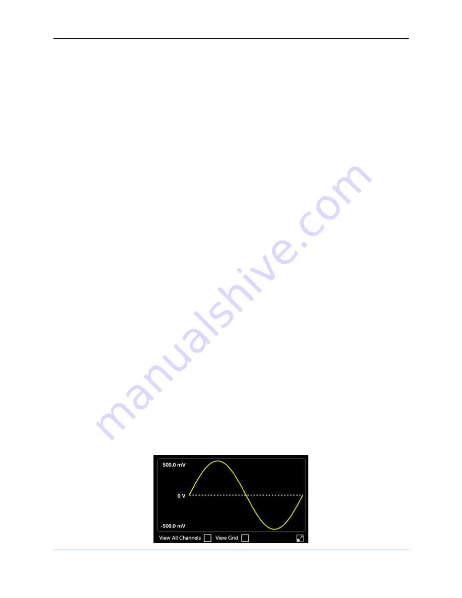
Graph Area
The graph area displays the Output channel waveform with a vertical legend that shows the minimum
and maximum voltage levels and the offset.


