background image

Follow these steps to configure the system to run Sherlock:
1. Connect cameras as shown in the hardware installation.
2. Verify a valid license is installed (run License Manager).
3. Run the 

iDiscover

program to detect and configure cameras connected to the 

system (icon shortcut on the desktop).

4. Run the 

Sapera CamExpert

utility if you want to change settings in any of the Genie 

Nano cameras such as exposure,  strobe or white balance. (does not apply to PIC-

2592.)

5. Run the 

Sapera Acquisition Wizard

to verify Genie Nano cameras are shown as 

expected and save the configuration file SaperaLTDrv.ini by clicking the “save” 

button. (does not apply to PIC-2592)

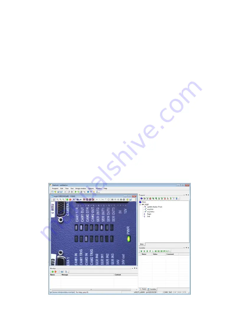
6. Launch Sherlock using the shortcut on the desktop (Sherlock GUI shown below). 
7. Go to the Options menu and select Acquisition. In the “Configure Driver Loading” 

section enable “Sapera LT” for Genie cameras. 

8. Enable “Ifc” for the PL-USB or PIC-2592 cameras. Edit the “IfcDrv.ini” file to point to 

a valid PL-USB or PIC2592 configuration file. A full path is required. Refer to the PL-

USB Installation Manual, or the PIC2592 Quick Start Guide. 

Note:

Sherlock will fail 

to run if you enable Ifc but fail to point to a valid configuration file! 

9. Close and reopen Sherlock. Driver changes only take effect when Sherlock opens.

Sherlock Setup 

18

GV 400 Installation

Version 1.3; 2020-5-14

Содержание GV 400

Страница 1: ...GV 400 Vision System Installation Manual 405 00083 00 1 GV 400 Installation Version 1 3 2020 5 14 ...

Страница 2: ...nd the related documentation are prohibited except with the express written consent of Teledyne Imaging The information in this document is subject to change without notice Teledyne Imaging makes no representations or warranties with respect to the contents of this manual and specifically disclaims any implied warranties of merchantability or fitness for a particular purpose Teledyne Imaging assum...

Страница 3: ...vide reasonable protection against harmful interference in a residential installation This equipment generates uses and can radiate radio frequency energy and may cause harmful interference to radio communication Other CFR 21 Part 11 This product provides tools needed for users to implement an auditing program that could be in compliance with CFR 21 Part 11 These tools include System or software b...

Страница 4: ...he enclosure Electro Static Discharge Avoid the damage that ESD can cause Never expose the internal electronics to a potentially hazardous environment by opening the enclosure Doing so may cause serious damage User Service Warning This product has no field replaceable components Tampering with the unit will void the product warranty Warranty Teledyne Imaging warrants the GV 400 Vision System again...

Страница 5: ... 12 Software Getting Started 13 Directory Structure 13 The License Manager 14 iNspect Express Setup 15 iNspect Express Configurator 16 iDiscover Genie 17 Sherlock Setup 18 Sapera CamExpert 19 Sapera Acquisition Wizard 20 Changing Camera Order 21 Enhanced Write Filter 22 Acronis True Image Software 22 Specifications GV 400 Specifications 24 Mechanical Drawings 25 I O Modules PL USB Overview 26 DCI ...

Страница 6: ...s manual will assist you with the installation and setup of your GV 400 product and the embedded inspection software It describes what the product supports and how to connect the external interfaces If your questions are not answered in this reference please contact your local Teledyne Imaging representative In addition to this installation manual support is available as follows 1 Fingertip help i...

Страница 7: ...t Express 03 or Sherlock 04 embedded software and DIN mounting hardware Standard components ship with every GV 400 Vision System 7 Component Description A CAM G3 XXXX XX Genie Nano Series GigE cameras A CAB GE X GigE CAT5e camera cables video data network communication A PL USB USB breakout module for camera interfacing and additional I O A DCI 101 Breakout module for camera interfacing A CAB G3 I...

Страница 8: ...e GV 400 Vision System 1 2 3 5 Rear Connections 1 Reset button recessed behind the front plate Use blunt pointed object and hold for 5 seconds to reset the unit 2 Power connector Supports 12 36 VDC 60W 3 VGA display port 4 HDMI display port preferred 5 Two USB 2 0 ports Typically used to connect Keyboard Mouse or flash drive 4 8 GV 400 Installation Version 1 3 2020 5 14 ...

Страница 9: ...hernet camera ports Note POE cannot be disabled Default IP settings are as follows these can optionally be changed through the Windows network change adapter settings interface Marking Connection CAM1 Static IP Address 192 168 11 1 Camera port 1 CAM2 Static IP Address 192 168 12 1 Camera port 2 CAM3 Static IP Address 192 168 13 1 Camera port 3 CAM4 Static IP Address 192 168 14 1 Camera port 4 LAN ...

Страница 10: ... or color formatting Consult your Teledyne Imaging representative on applications requiring more than 4 cameras or high inspection speeds iNspect Express and Sherlock use different software drivers to interface to Genie Nano cameras iNspect Express uses a driver called IFC whereas Sherlock uses one called Sapera LT The setups associated with each will be described later in the manual Generally Sap...

Страница 11: ...nd to the PL USB 2 Power connections to the PL USB and GV 400 are not shown 3 Use A CAB GE X for camera Ethernet connections 4 Use A CAB G3 IO X for I O connections between Genie Nano and PL USB Camera Input2 is the expected trigger Output2 is the strobe Cable wiring diagrams appear in the PL USB Quick Start Guide and PL USB Install Manual USB link GV 400 Installation Version 1 3 2020 5 14 ...

Страница 12: ...ound to the DCI 101 2 Power connections to the DCI 101 and GV 400 are not shown 3 Use A CAB GE X for camera Ethernet connections 4 Use A CAB G3 IO X cables for Genie Nano I O Camera Input1 is the expected trigger Cable wiring diagrams appear in the DCI 101 Quick Start Guide 5 Use one A DCI 101 for every 2 cameras 12 DCI 101 modules GV 400 Installation Version 1 3 2020 5 14 ...

Страница 13: ...pply when iNspect Express is installed with the default option for all users The path becomes Users Teledyne AppData Local when installed for the current user only GV 400 Installation Version 1 3 2020 5 14 iNspect Express Program Files and Directories iNpsect Express Configurator C Program Files Teledyne Dalsa iNspectExpress x64 iNspectExpressConfig exe iNspect Express C Program Files Teledyne Dal...

Страница 14: ...Nspect Express License Manager Start All Programs Teledyne DALSA Sherlock License Manager In this example System 2044499585 is the system drive and Sapera LT Board 9010044 is a Genie Nano Camera Both Sherlock and iNspect Express are licensed on the System drive Your system may have only one of these licenses If the license does not reflect what you purchased consult your Teledyne Imaging sales rep...

Страница 15: ... Open the iNspect Express Configurator and configure preferences Select GigE in the camera menu 4 Click on the iDiscover button to detect and configure cameras connected to the system 5 Save Camera set select which connected cameras you want to use 6 Close iDiscover and launch iNspect Express run panel shown below iNspect Express Setup 15 GV 400 Installation Version 1 3 2020 5 14 ...

Страница 16: ...features are peculiar to the iNspect Express software and are detailed in the software users manual From the camera selector tool you can launch both iDiscover and iNspect Express as shown below To launch the emulator simply select the Emulator and launch iNspect Express The iNspect Express Configurator Click to launch iDiscover Genie Click to launch iNspect Express 16 GV 400 Installation Version ...

Страница 17: ...y the camera IP address to match the camera port IP segment at the top Note Conflicting IP addresses will be designated by a red camera icon in the detected camera menu Click the Apply button to save changes The Genie and PIC 2592 cameras will reappear configured at the new address Select cameras to use in your iNspect Express configuration by clicking and moving them to the left panel using the a...

Страница 18: ... configuration file SaperaLTDrv ini by clicking the save button does not apply to PIC 2592 6 Launch Sherlock using the shortcut on the desktop Sherlock GUI shown below 7 Go to the Options menu and select Acquisition In the Configure Driver Loading section enable Sapera LT for Genie cameras 8 Enable Ifc for the PL USB or PIC 2592 cameras Edit the IfcDrv ini file to point to a valid PL USB or PIC259...

Страница 19: ...C 2592 camera Refer to the PIC 2592 Quick Start Guide You can configure the camera to load either your saved settings or the factory settings at power up The preferred method is to save your settings to both the camera and a configuration file Sherlock can load a configuration file at startup If multiple configurations are needed you can save them to different camera configuration files Some examp...

Страница 20: ...e PIC 2592 Quick Start Guide The Sherlock application uses the settings stored in the camera or in camera configuration files You can also use Sherlock instructions to change Gain Exposure shutter time or Strobe pulse width IO Camera SetNumberFeature programmatically When you launch the wizard you will see the dialog below All cameras connected to the GV 400 should be listed in the device window C...

Страница 21: ...d paste the camera names in the correct order Or correct the references to Server0 and Server1 to match the order you want your cameras to follow Notice that each Server appears twice in the configuration file For example Server0 Server0_Device0 Server1 and Server1_Device0 Each time you run Sherlock it will use the order saved in the SaperaLTDrv ini file that is created by the wizard The order doe...

Страница 22: ...ated in the C IPD Install Files directory The utility has a GUI graphic user interface for displaying status and setting the filter Changes take effect on the next system reboot Note If you have run the filter and not yet rebooted it is still showing the current status from when you booted not what you have set for the next reboot Windows Unified Write Filter 22 GV 400 Installation Version 1 3 202...

Страница 23: ...ed Restoring the factory image will all files and configuration changes Back up your files before restoring the factory image 1 Reboot the GV400 system 2 When the Teledyne logo is displayed tap the Delete key continuously to enter BIOS 3 Use the right arrow key to select the Save and Exit tab 4 Use the down arrow key to select Acronis loader under the Boot Override options and press the Enter key ...

Страница 24: ... no flow control USB 4 x USB 2 0 2 front and 2 rear I O External via PL USB module LED status 2 indicators for Power and HDD Display VGA HDMI VGA DS 15 pin female supports up to 1600x1200 HDMI 3840x2160 30Hz Power 24V 60W 2 pin connector Recessed Reset button Use pointed object to push and hold for 5 seconds Cooling Fanless Passive heatsink Mechanical Material Machined Aluminum with paint finish M...

Страница 25: ...GV 400 Mechanical Dimensions 25 GV 400 Installation Version 1 3 2020 5 14 Side View Top View Front View ...

Страница 26: ...spect Express and Sherlock The product is DIN mountable and connects to the GV 400 through a single USB cable Refer to the PL USB Installation Manual for details and camera wiring diagrams A copy is provided on the GV 400 system drive Note The PL USB driver is already installed on all GV 400 systems PL USB Configuration files are also included on all GV 400 systems at C VAGenieX64 Config PL USB Ov...

Страница 27: ...e cameras 24V models Note The DCI 101 does not add conditioning i e noise filtering to the input signals this is done inside the camera All inputs and outputs are passed between camera and panel connectors through the isolation barrier Refer to the DCI 101 Quick Start Guide for details and camera wiring diagrams A copy is provided on the GV 400 system drive Note There is no software driver require...

Отзывы: