The Falcon4 Camera Overview
Falcon 4 Camera User's Manual
•
7
RXC
TXC
TX1
TX2
TX3
TX4
TX5
TX6
TXC
RXC
RX1
RX2
RX3
RX4
RX5
RX6
Data Lane 6
Data Lane 0
Command
Channel
Video
Channel
Link
Camera
(C2,7M1)
Frame Grabber
(C2,7M1)
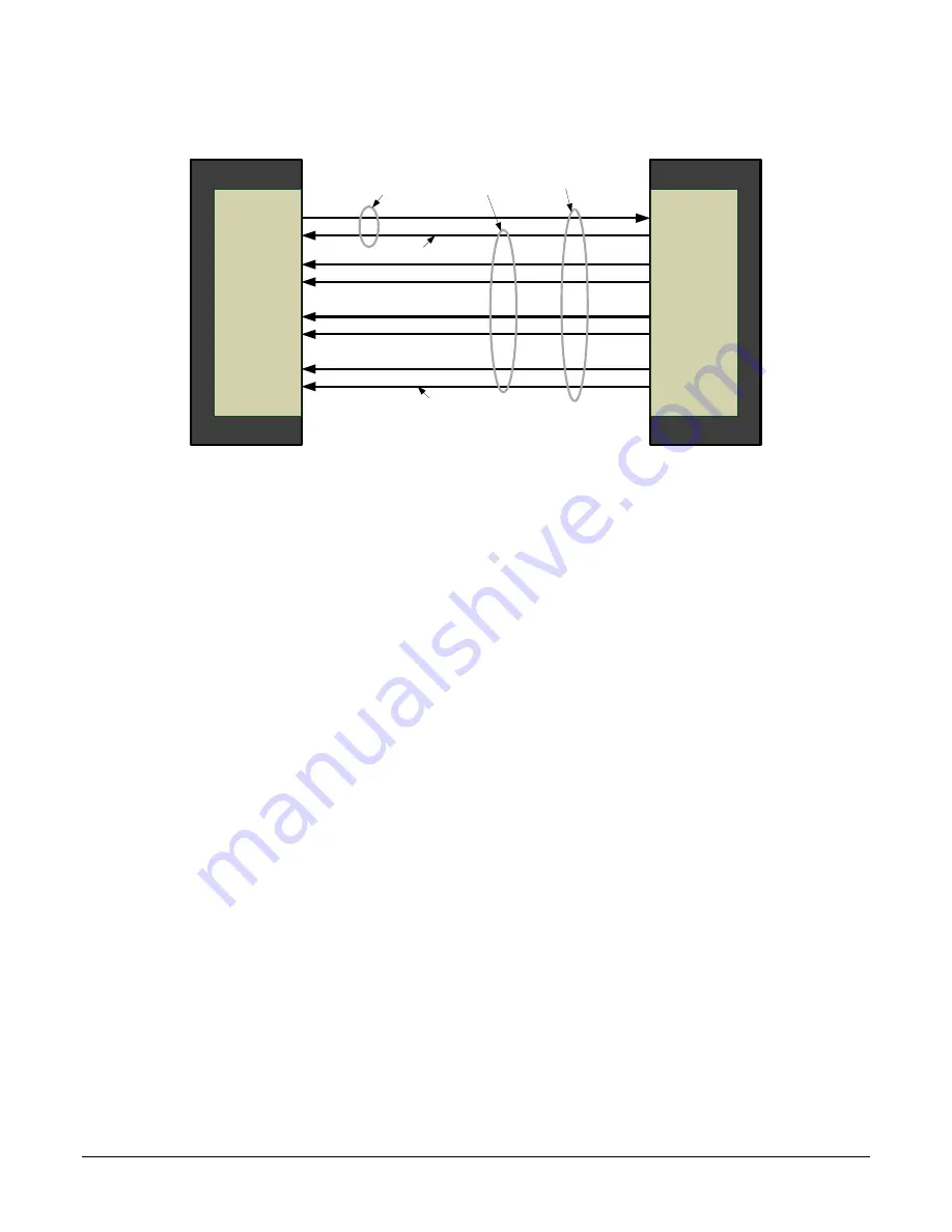
Figure 1. Single CLHS Connector Configuration
The command channel is used by the frame grabber to send command, configuration, and
programming data to the camera and to receive command responses, status, and image data from
the camera.
The designation C2, 7M1 defines the use of a SFF-8470 connector (C2) and up to 7 lanes of data
with 1 command channel using M-Protocol (8b/10b) at the default speed of 3.125 Gb/sec.
When using a CX4 Active Optical Cable fiber module, only the command channel and data lanes 0,
1, 2 and 3 (C2, 4M1) will be available, with an associated reduction in bandwidth. Use two fiber
modules to retain the full performance of the camera.
A feature of CLHS is that the initialization of the frame grabber automatically starts a discovery
process that will identify the lane configuration of the camera. This process is transparent to the
user and requires no action by the user to correctly configure the link.
Camera Link HS Transmission Characteristics
The camera data distribution supports 1 cable with single ROI capability. The single ROI is
customer entered and transmitted across all seven data lanes. There is a minimum of 96 pixels per
data lane used.
CLHS limits the start and stop location of the ROI to a multiples of 32 pixels. The maximum line
rate is limited by the sensor when not limited by the CLHS cable or by the PCIe transfer. The sensor
is limited to a 125 kHz maximum line rate.
The CLHS cable has approximately 2.1 GByte / sec bandwidth for seven lanes. The XTIUM frame
grabber has about 1.6 GByte / sec across the PCIe bus.
The Frame Grabber is able to store rows in order to perform a “burst-type” operation. CLHS packs
the bits, while the frame grabber unpacks 12 bit data into 16 bit data across the PCIe bus.
Preliminary


