background image

LabMaster 10 Zi-A Getting Started Guide

19

BASICS

MAUI with OneTouch 

Touch, drag, swipe and flick can be used to create and change setups with one touch. Just as you change the display by using the setup dialogs, you 

can change the setups by moving different display objects. Use the setup dialogs to refine OneTouch gestures to precise values.
As you drag & drop, valid targets are outlined with a white box. When you’re moving over invalid targets, you’ll see the “Null” symbol ( Ø ) under your 

finger tip or cursor. 

Turn On

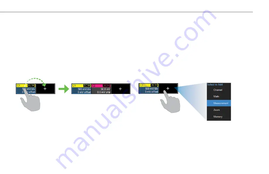
To turn on a new channel, math, memory, or zoom trace, drag any 

descriptor box of the same type to the 

Add New (“+”) box

. The next trace 

in the series will be added to the display at the default settings. It is now 

the active trace.

If there is no descriptor box of the desired type on the screen to drag, 

touch the Add New box and choose the trace type from the pop-up menu.
To turn on the Measure table when it is closed, touch the Add New box 

and choose Measurement. 

NOTE: 

AC1M and DC1M coupling shown in illustrations is not available on LabMasters

Содержание LabMaster 10 Zi-A

Страница 1: ...LabMaster 10 Zi A Oscilloscope Systems Getting Started Guide...

Страница 2: ...is strictly prohibited Customers are permitted to duplicate and distribute Teledyne LeCroy documentation for internal educational purposes Teledyne LeCroy is a trademark of Teledyne LeCroy Inc Other...

Страница 3: ...oy com support techlib Introduction Introducing LabMaster 10 Zi A 2 Safety 3 Overview Front of MCM Zi A Master Control Module 4 Back of MCM Zi A Master Control Module 5 Front of LM10xxZi A Acquisition...

Страница 4: ...drop actions or use familiar touch screen gestures like pinch swipe and flick to intuitively interact with the instrument Mixed Signal Option The HDA125 High Speed Digital Analyzer enables up to 18 i...

Страница 5: ...arest object Keep the underside clear of papers and other objects Exercise care when lifting and carrying Do not remove the covers or inside parts Refer all maintenance to qualified service personnel...

Страница 6: ...to control the oscilloscope in addition to the touch screen D The Power button makes all components operational or puts them in standby mode It only works when all cabling is correct E Fast Edge outp...

Страница 7: ...D AC Power inlet and buzzer reset switch Press the button to reset power on the system and silence the buzzer in case of over temperature shut down E USB 3 1 ports 4 for high speed peripherals and Et...

Страница 8: ...r or Pass Fail result D LED channel indicators show selection of standard A or high bandwidth B channel E Channel ON FF buttons F Ground connection for wrist strap G Two 1 85 mm interfaces are added t...

Страница 9: ...ter 10 Zi A Getting Started Guide 7 Back of LM10xxZi A Acquisition Modules A SMA 10 GHz Clock input B PCIe 1 Lane SYNC input C PCIe 4 Lane DATALINK output D AC power inlet with cable clamp A B C D OVE...

Страница 10: ...ton enables or disables touch screen functionality F Clear Sweeps resets math and measurement counters G Zoom creates zooms of all open channel traces All the knobs on the front panel function one way...

Страница 11: ...ALINK input on the back of the control module to the DATALINK output on the back of the acquisition module 4 Repeat Steps 1 3 for each acquisition module in your system using the inputs outputs that c...

Страница 12: ...right 3 Connect from the remaining SMA 10 GHz Clock PCIe 1 Lane SYNC and PCIe 4 Lane DATALINK connectors on the CMH 20 back panel to the connectors on the corresponding acquisition modules Each set of...

Страница 13: ...to unplug the power cords We recommend unplugging the system if it will remain unused for a long period of time CAUTION Do not change the Windows Power setting to System Standby or System Hibernate D...

Страница 14: ...ote dialog and use the Windows networking dialogs to configure the device address Go to File File Sharing to configure email Remote Control You can control the instrument over a LAN using VICP TCP IP...

Страница 15: ...e oscilloscope is networked LabNotebooks reports and other user data files can be emailed directly from the instrument or saved to accessible network devices Files can also be transferred to a USB dri...

Страница 16: ...up Dialogs Using the Touch Screen Display The entire display is active Use your finger to touch drag and drop swipe pinch and flick Many controls that display information also work as buttons to acces...

Страница 17: ...detail as more are opened The Add New box sits next to the trace descriptor boxes Use it to turn on new traces or the Measure table See MAUI with OneTouch on p 15 Timebase and Trigger descriptor boxes...

Страница 18: ...256 Vertical Levels By default the oscilloscope has the Auto grid mode enabled Auto adds a grid for each new trace up to 16 grids until no more grids are available Other grid modes create a fixed numb...

Страница 19: ...y and Persistence The trace style can be set to a series of separate sample Points or a continuous vector Line Grid Intensity makes the grid lines dimmer or brighter relative to the trace When more da...

Страница 20: ...ces Trace Descriptor Boxes Channel C1 Cn Zoom Z1 Z12 Math F1 F12 Memory M1 M12 and Digital Digital1 Digital4 descriptor boxes appear along the bottom of the grid area when a trace is turned on Descrip...

Страница 21: ...er invalid targets you ll see the Null symbol under your finger tip or cursor Turn On To turn on a new channel math memory or zoom trace drag any descriptor box of the same type to the Add New box The...

Страница 22: ...e onto the target descriptor box You can also drop it on the Source field of the target setup dialog To change the source of a measurement drag and drop the descriptor box of the desired source onto t...

Страница 23: ...To change the trigger source channel drag and drop the desired channel Cn descriptor box onto the Trigger descriptor box The trigger will revert to the last trigger set on that channel To place horizo...

Страница 24: ...escriptor box onto the target memory Mn descriptor box Pan To pan a trace activate it to bring it to the forefront then drag the waveform trace right left or up down If it is the source of any other t...

Страница 25: ...ce touch then drag diagonally to draw a selection box around the portion of the trace you want to zoom Touch the Zn descriptor box to open the zoom factor controls and adjust the zoom exactly To turn...

Страница 26: ...h to toggle between coarse and fine scale adjustments Vertical Channel Gain Setting Offset Setting Pre Processing Summary List Coupling Vertical Cursor Positions Sweeps Averaged Segment ChannelSync Ca...

Страница 27: ...New box and choose Channel Touch new Cn descriptor to open the Cn setup dialog BASICS Enter Attenuation for passive and other vendors probes Enter Volts div and Offset Rescale channel trace or change...

Страница 28: ...aise lower group Vertical Position the top of lowest bit relative to center Turn Volts to raise lower Group Height the total Vertical divisions occupied by group Digital Descriptor Box Digital Memory...

Страница 29: ...Digitaln setup dialog BASICS From the Touch Screen Choose Display Mode of individual lines bus trace or both Line Activity indicators show the state of each line high low or transitioning Optionally c...

Страница 30: ...negative Delay time The front panel Time knob also controls the Horizontal Scale of zoom math and memory traces allowing you to zoom in to see more detail or zoom out to see the bigger picture BASICS...

Страница 31: ...on From the Touch Screen Touch the Timebase descriptor to open Timebase setup dialog Optionally enter Delay negative time before trigger or positive time after trigger event to show Select Sampling Mo...

Страница 32: ...re met unless postponed by a Holdoff count of time or number of trigger events Trigger types and modes are described at more length in the LabMaster Oscilloscope Systems Operator s Manual From the Fro...

Страница 33: ...Touch Trigger descriptor to open Trigger setup dialog Choose trigger Type Choose trigger Source channel Set trigger Level or Find Level based on the input signal Icon summarizes the trigger selection...

Страница 34: ...lay a magnified portion of another trace Any trace can be zoomed although Zoom is most useful for channel traces as it allows you to see the source at the original Timebase at the same time as the Zoo...

Страница 35: ...p dialog touch Action Toolbar Zoom button to create a new zoom of just that source trace Zoom descriptor opens Zoom dialog to make other adjustments Draw a Zoom box over a portion of the source trace...

Страница 36: ...ere the cursor intersects the waveform and the delta of the two lines From the Front Panel From the Touch Screen Cursors Cursor Setup opens the Cursor dialog Touch and drag cursor to reposition Vertic...

Страница 37: ...histogram trend or track of the measurement over time Measure Measure Setup opens the Measure dialog Touch Measure column to re open Measure dialog if closed Pn dialogs to configure user defined measu...

Страница 38: ...sult of applying a mathematical function e g Sum Product FFT to one or more source traces Operations can be chained by using one math function as a source for the other The math trace always opens in...

Страница 39: ...M1 M12 Choose Math Memory Setup On the Mn tab select the trace you want stored in Copy From Waveform then touch Copy Now Optionally add Notes or Labels to the stored memory Then drag the descriptor bo...

Страница 40: ...ng complex user defined patterns and events in the data stream BASICS Select Source trace and Protocol View decoding on the colored overlays When there is more data than fits in a table cell touch the...

Страница 41: ...of scan modes similar to trigger setups enable a quick search for events of interest The results are time stamped tabulated and can be selected for individual viewing Color overlays mark events on the...

Страница 42: ...factory calibration as part of your routine maintenance LabMaster 10 Zi A incorporates automatic calibration routines so that it maintains specified performance Always warm the oscilloscope at least 2...

Страница 43: ...al minutes depending on the length of time since your last update Do not power down the oscilloscope at any point during the installation process Switching Windows Users Windows 10 oscilloscopes are b...

Страница 44: ...to avoid damage in transit Do not include the manual 4 Mark the outside of the box with the shipping address Be sure to add ATTN RMA code assigned by Teledyne LeCroy FRAGILE 5 If returning a product...

Страница 45: ...edyne LeCroy shall not be obligated to service a product that has been modified or integrated where the modification or integration increases the task duration or difficulty of servicing the instrumen...

Страница 46: ...etic Field 3 Vrms 0 15 MHz 80 MHz EN 61000 4 11 2004 Mains Dips and Interruptions 0 1 cycle 70 25 cycles 0 250 cycles 4 5 1 To ensure compliance with all applicable EMC standards use high quality shie...

Страница 47: ...the LabMaster 10 Zi A are on our website at teledynelecroy com patents Safety Compliance EC DECLARATION OF CONFORMITY LOW VOLTAGE The system meets intent of EC Directive 2014 35 EU for Product Safety...

Страница 48: ...2021 Teledyne LeCroy Inc All rights reserved 933204 00 Rev A February 2021...

Отзывы: