GB
GB
36
37
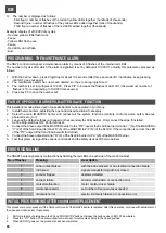
PROGRAMMING THE MAINTENANCE ALARM
The SN24 control unit signals a maintenance alarm by means of 6 flashes of the internal red LEDs.
The number of cycles after which the alarm is signalled is set by default at 100,000. To modify this parameter, proceed as
follows:
1.
With the barrier down, press Prog/Stop for about 10 seconds (after three seconds LD1 illuminates; keep pressing
until LD1 goes out again)
2.
The maintenance alarm has now been deleted so it has to be reprogrammed.
3.
The number is set in multiples of 10,000. Press P/P to increase the flashes of LED LD1 (the maximum number of
flashes is 10, corresponding to 100,000 manoeuvres).
4.
Press key P3 to save the number set.
3)
The number is displayed as follows:
- First figure: number of flashes of the red and yellow LEDs together (hundreds of thousands)
- Second figure: number of flashes of the yellow LEDs added together (tens of thousands)
- Third figure: number of flashes of the red LEDs added together (thousands)
Example: display of 210,000 duty cycles.
- Red and yellow LEDs flash twice
- Pause
- Yellow LEDs flash once
- Pause
- Red LEDs do not flash
- End
PAIR OF OPPOSITE BARRIERS, MASTER-SLAVE FUNCTION
This installation mode allows a pair of opposite barriers to be operated in synchrony.
1.
Install the two barriers, adjusting the open and closed positions if necessary.
2.
Select the main (MASTER) barrier and connect all the system functions (controls, radio receivers, safety devices,
photocells, etc.) to it.
3.
Leave all the default settings unchanged on the secondary (SLAVE) barrier. Only connect the edge, if installed.
Set the 8 dip-switches ON. Perform a reset.
4.
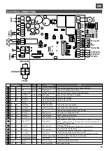
Connect the Slave output of the MASTER barrier to the “P/P” input of the SLAVE barrier, terminal “-” (5) of the MASTER to
“C” (22) of the SLAVE and terminal “D” (6) of the MASTER to P/P (19) of the SLAVE. If the connection is correct, the LED
of the “P/P” output of the SLAVE barrier will start to flash.
5.
Connect the Slave output, terminal “D” (6), of the SLAVE barrier to “PA” (20) of the MASTER barrier.
6.
Test the system, trying out the various commands and the safety devices of the two barriers.
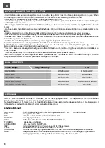
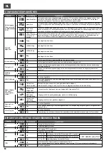
The SNAP4 barrier signals any malfunctions by flashing the red LEDs on each side of the control cabinet:
ERROR SIGNALLING
14
1
2
3
4
5
with the edge pressed or an electrical connection failure
edge contact broken
No. of flashes
Description
Meaning
rod forced
signals manual forcing with bar closed
encoder tripped
obstacle detected
encoder failure
encoder malfunction or connection error
motor control driver failure
mofset malfunction
6
7
maintenance alarm
set number of manoeuvres exceeded
electric limit switch failure or connection error
limit switch error
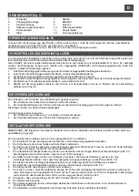
INITIAL PROGRAMMING AFTER control unit REPLACEMENT
This procedure is only necessary if the SN24 control unit of the SNAP4 barrier is replaced. After this operation, continue with adjustment of
the open and closed points, if necessary.
1.
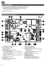
Perform a reset by holding down the P3 and PROG/STOP buttons. Release the buttons when LED LD1 illuminates.
2.
Press the “P/P” button. The barrier will perform a series of movements and stop in the closed position.
3.
When LED LD1 goes out, the procedure has been completed.
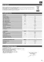
TECHNICAL DATA
Motor voltage
Max. motor current
Maximum motor power
Maximum torque
Max. rod length
Max. operating angle
Operating time
Duty cycle intensity
Encoder
Electric limit switches
Lubricating grease
24
Vdc
MOTOR
U.M.
A
12
W
300
Nm
600
4250
°
mm
3-6
100
sec.
intensive
Y
Y
TS10
Model
Power supply voltage
Max. current
Electronic deceleration
Compatible with Sun Power
SN24
CONTROL UNIT
U.M.
Vac
230
A
1,5
Y
Y
Operating temperature
Degree of protection
Weight
-20 +55
°C
GENERAL DATA
U.M.
IP
54
Kg
50
DISPOSAL
This product is made up of various components that could contain pollutants. Dispose of properly!
Make enquiries concerning the recycling or disposal of the product, complying with the local laws in
force.
EC DECLARATION OF CONFORMITY
The manufacturer: Telcoma srl
via L. Manzoni, 11 - 31015 - Z.I. Campidui Conegliano (TV) - ITALY
DECLARES that the product: SNAP4
complies with the following EEC directives:
-EMC Directive 2004/108/EC
-Low Voltage Directive (LVD) 2006/95/EC
Conegliano, 17/02/2012
The Legal Representative
Ennio Ambroso
Содержание RAPPER4TL
Страница 4: ...I F E GB D NL 270 Fig D min 200 mm 310 240 m in 400 227 160 min 350 Fig E1 Fig E2 4...
Страница 5: ...I F E GB D NL Fig F Fig G 4 5...
Страница 54: ...NOTE...
Страница 55: ......

