Telcoma Automations RAPPER4TL Скачать руководство пользователя страница 8

I

BARRIERA SINISTRA

Per trasformare la barriera da DESTRA a SINISTRA procedere come segue:
1.

Spostare la molla dalla posizione destra alla posizione sinistra (fig. G1)

2.

Invertire i fili del motore nella centralina (35 con 36 , pagina successiva)

3.

Invertire fili 14 con 16 (finecorsa elettrici)

Procedere quindi con l’installazione.

I

8

9

FCS

D

-

TPR.OPEN
FotoRIC.

JOLLY

SLAVE

RIC.AUT.

PRELAMP.

REG.VEL.

P/P

U

S

1

JCC

LD1

RS

P/P

PA

TEST

TR1

FCS

C2

24FT

24V

NA

COM

NC

Slave

LDA

TPR

+

-

P/P

PA

PC

C

CC

STP

FT

CSB

+

-

+

-

-

+

D

M

M

FC1

FC2

C1

ON

CC

STP

FT

TPR

+

-

Reset

A

N

T

.

P3

1

2

3

4

5

6

7

8

9

10

11

12

P/P

STOP

PROG.

SCHEDA RADIO OC

+

1

O

N

+

+

23

1

2

3

4

22

21

20

19

18

5

7

8

13

12 11

14

15

16

9

10

6

17

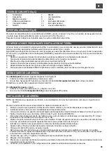
DESCRIZIONE DELLE PARTI (Fig. H)

1)

Fusibile ausiliari 24V (2A fast)

2)

Fusibile motore 24V (10A fast)

3)

Connettore luci LED interne

4)

Uscita motore 24V

5)

Morsettiera collegamento encoder

6)

Jumper TEST e FCS

TEST: togliendo questo jumper si disabilitano gli ingressi 
sicurezze (part. 7) con barriera chiusa.
FCS: togliere questo jumper se viene usato un micro-
switch di sicurezza sulla porta (ingresso 26 - NC)

7)

Morsettiera ingressi sicurezze e alimentazione
ausiliari

8)

Morsettiera ingressi comando

9)

Jumper JCC

10) Dip-Switch disabilitazione sicurezze
11) Dip-Switch funzioni

12) Pulsanti programmazione
13) Connettore luci LED interne
14) Jumper RESET centralina
15) Jumper selezione modalità canale 1 ricevitore OC2:

P/P: passo/passo
PA: comando apre
Il secondo canale è sempre comando chiude.

16) Connettore per ricevitore tipo OC2
17) Trimmer regolazione rallentamento in

apertura

18) Ingresso antenna radio
19) Collegamento di TERRA
20) Ingresso finecorsa motore
21) Uscita contatto US1 (jolly)
22) Uscita luci asta, comandi SLAVE e TPR
23) Ingresso 24Vdc alimentazione centralina

Fig. H

COLLEGAMENTI ELETTRICI

FCS

D

-

TPR
FotoRIC.

JOLLY

SLAVE

RIC.AUT.

PRELAMP.

REG.VEL.

P/P

U

S

1

JCC

LD1

RS

P/P

PA

TEST

TR1

FCS

C2

24FT

24V

NA

COM

NC

Slave

LDA

TPR

+

-

P/P

PA

PC

C

CC

STP

FT

CSB

+

-

+

-

-   filo BLU

+  filo VERDE

D  filo BIANCO

FC1

FC2

C1

ON

CC

STP

FT

TPR

+

-

Reset

A

N

T

.

P3

1

2

3

4

5

6

7

8

9

10

11

12

P/P

STOP

PROG.

SCHEDA RADIO OC

+

1

O

N

+

+

24

V

d

c

M

O

TO

RE

M

1

2

3

4
5

6

7

8

9
1

0
1

1

1

2

1

3

1

5

1

4

1

6

1

7

1

8

1

9

2

0

2

1

2

2

2

3

2

4

2

5

2

6

2

7

2

8

2

9

3

0

3

1

3

2

3

3

3

4

3

5

3

6

EN

CO

DE

R

+

-

+

-

le

d

as

ta

u

sc

ita

 U

S

1

8A

 2

30

V

C2

FC1

FC2

C1

1

3

1

5

1

4

1

6

finecorsa

chiusura

apertura

FT
STOP

Costa in chiusura

Contatto porta

Pulsante CHIUDE
Pulsante APRE
Pulsante P/P

Alimentazione
fotocellule

Morsetto n.

1

5

7

9

10

10

11

12

13

14

15

16

17

18

19

22

20

22

21

23

27

24

27

25

27

26

27

28

29

30

31

32, 33, 34

35

36

TPR

comando SLAVE

Luci ASTA

Uscita US1

Uscita US1

TERRA

Contatto NC

Contatto NC

Antenna Radio

Pulsante NA

Pulsante NA

Pulsate NA

Costa 8K2 / N.C.

Pulsante NC

Contatto NC

Contatto N.C.

Ausiliari

Ausiliari

Encoder

Motore

24Vdc

24Vac

24V

100 mA


Alimentazione Centralina

Assenza linea

uscita comandi SLAVE

Illuminazione ASTA

Uscita jolly NC

Uscita jolly NA

Contatto di TERRA

Finecorsa APRE

Finecorsa CHIUDE

17 Calza, 18 Centrale

Comando Passo/Passo

Comando Chiude

Comando Apre

Costa in Chiusura

Comando Stop

Fotocellula in chiusura

Contatto porta

Alimentazione fotocellule

Alimentazione

32 - / 33 + / 34 D

Uscita Motore 24V

Dispositivo

V

I max

Funzione

Note

Collegare al secondario del trasformatore

Collegare all’uscita alimentazione dalla scatola alimentatore

collegare alla centralina della seconda barriera (SLAVE)

Collegare alle luci LED dell’asta, se presenti

Finecorsa nei pressi dell’apertura

Finecorsa nei pressi della chiusura

Collegare un’antenna per 433 MHz (50 Ohm)

Vedi tabella di configurazione dip-switch

Avvia l’apertura della barriera

Avvia la chiusura della barriera

Ingresso abilitato in chiusura. Possibilità di collegare coste 8K2 (JCC 
chiuso) oppure un contatto N.C. (JCC aperto). Se non viene 
utilizzato, aprire JCC e portare in ON dip-switch CC (dip 3 di part. 10)

Blocco di tutte le funzioni. Se non utilizzato, portare in ON il dip-
switch STP (dip 2 di part. 10)
Durante la chiusura inverte la marcia.
Se non utilizzata, portare in on il dip-switch FT (dip 1 di part. 10)
Collegare questo ingresso al micro-switch di sicurezza della porta.
Se non utilizzato, ponticellare l’ingresso (filo tra 26 e 27)

Tensione presente solo quando la barriera non è chiusa

Tensione permanente

Connessione al Motore

2

3

4

6

8

22

24Vdc

1A max

24Vdc

1

A

 m

a

x

.

Dati di contatto: 8A 230V

Dati di contatto: 8A 230V

10 A

32 BLU, 33 VERDE, 34 BIANCO

A

n

te

n

n

a

Содержание RAPPER4TL

Страница 1: ...ation et la programmation pag 14 BARRERA ELECTROMEC NICA Instrucciones de uso y de programaci n pag 22 ELECTROMECHANICAL BARRIER Operation and programming instructions pag 30 ELEKTROMECHANISCHE SCHRAN...

Страница 2: ...de passage utile 4000 mm E ancho de paso libre 4000 mm GB usable opening 4000 mm D Nutzbarer lichter Durchgang 4000 mm NL nuttige breedte doorgang 4000 mm I Misure espresse in mm E Medidas expresadas...

Страница 3: ...QUADRO D ASSIEME TABLEAU D ENSEMBLE CUADRO DEL CONJUNTO GENERAL ASSEMBLY GESAMTANSICHT OVERZICHTSTEKENING I F E GB D NL 7 6 9 8 3 4 2 1 5 10 1 11 12 Fig C I F E GB D NL 3...

Страница 4: ...I F E GB D NL 270 Fig D min 200 mm 310 240 m in 400 227 160 min 350 Fig E1 Fig E2 4...

Страница 5: ...I F E GB D NL Fig F Fig G 4 5...

Страница 6: ...i all automazione e nel caso ve ne siano avvertire immediatamente l installatore Di non far giocare i bambini nelle immediate vicinanze dell automazione Predisporre un piano di manutenzione dell impia...

Страница 7: ...zione elettrica e di sicurezza 2 Installare la barriera a terra nei modi precedentemente descritti 3 Portare la barriera in posizione di asta abbassata sbloccando l asta Il lato del bilancino su cui f...

Страница 8: ...nettore luci LED interne 4 Uscita motore 24V 5 Morsettiera collegamento encoder 6 Jumper TEST e FCS TEST togliendo questo jumper si disabilitano gli ingressi sicurezze part 7 con barriera chiusa FCS t...

Страница 9: ...Passo Passo Comando Chiude Comando Apre Costa in Chiusura Comando Stop Fotocellula in chiusura Contatto porta Alimentazione fotocellule Alimentazione 32 33 34 D Uscita Motore 24V Dispositivo V I max F...

Страница 10: ...per Lampeggiante Apre Chiude alta Contatto per Luce di cortesia Apre Stop Chiude Il lampeggiante viene alimentato contemporaneamente al motore Funzione esclusa Dopo una apertura completa la centrale...

Страница 11: ...ere pi volte P P per spostare il punto verso l apertura oppure P3 per spostarlo verso la chiusura 9 Premere PROG STOP per memorizzare il punto prescelto 10 Portare il gommino antivibrante in appoggio...

Страница 12: ...era secondaria SLAVE lasciare tutto come da fabbrica Collegare solamente la costa se presente Mettere il dip 8 in posizione ON Fare un reset 4 Collegare l uscita Slave della barriera MASTER all ingres...

Страница 13: ...funzionamento Grado di protezione Peso 20 55 C CARATTERISTICHE GENERALI U M IP 54 Kg 50 SMALTIMENTO Questo prodotto formato da vari componenti che potrebbero a loro volta contenere sostanze inquinant...

Страница 14: ...n y a pas de dommages visibles l automatisme et s il y en a avertir imm diatement l installateur de ne pas laisser les enfants jouer proximit imm diate de l automatisme Pr parer un plan de maintenanc...

Страница 15: ...sol suivant les indications qui pr c dent 3 Mettre la barri re dans la position lisse abaiss e et bloquer la lisse Le c t du balancier sur lequel est fix le ressort doit se trouver en haut Voir fig G...

Страница 16: ...ED internes 4 Sortie moteur 24V 5 Bornier connexion encodeur 6 Cavalier TEST et FCS TEST en enlevant ce cavalier on d sactive les entr es s curit part 7 avec barri re ferm e FCS enlever ce cavalier si...

Страница 17: ...de Fermeture Commande Ouverture Bord sensible en fermeture Commande Stop Photocellule en fermeture Contact porte Alim photocellules Alimentation 32 33 34 D Sortie Moteur 24 V Dispositif V I max Foncti...

Страница 18: ...pour Clignotant Ouv Ferm haute Contact pour cl automatique Ouv Stop Ferm Le clignotant est aliment en m me temps que le moteur Fonction exclue Apr s une ouverture compl te la logique de commande refer...

Страница 19: ...ture 9 Presser PROG STOP pour m moriser le point choisi 10 Mettre le joint antivibratoire en appui sur le balancier 11 D bloquer la lisse et la porter au point d quilibre environ 45 degr s 12 Abaisser...

Страница 20: ...ion ON Faire une r initialisation 4 Connecter la sortie Slave de la barri re MASTER l entr e P P de la barri re SLAVE La borne 5 de la MASTER l entr e C 22 de la SLAVE et la borne D 6 de la MASTER l e...

Страница 21: ...onctionnement Indice de protection Poids 20 55 C Caract ristiques G n rales U M IP 54 Kg 50 ELIMINATION Ce produit est constitu de divers composants qui pourraient leur tour contenir des substances po...

Страница 22: ...ibles en la automatizaci n y si se encuentran de advertir de forma inmediata al instalador de no permitir que los ni os jueguen en los alrededores de la automatizaci n Preparar previamente un programa...

Страница 23: ...con las modalidades descritas anteriormente 3 Coloque la barrera en la posici n de m stil bajado desbloqueando el m stil El lado del balanc n sobre el que se ha fijado el muelle tiene que encontrarse...

Страница 24: ...ida motor 24V 5 Terminal de conexiones conexi n codificador 6 Jumper TEST y FCS TEST sacando este jumper se desactivan las entradas de los dispositivos de seguridad part 7 con barrera cerrada FCS saqu...

Страница 25: ...ral Comando Paso Paso Comando Cerrar Comando Abrir Banda en Cierre Comando Stop Fotoc lula en cierre Contacto puerta Alimentaci n fotoc lulas Alimentaci n 32 33 34 D Salida Motor 24V Dispositivo V I m...

Страница 26: ...s a Abrir Stop Cerrar La luz intermitente se alimenta de forma contempor nea con el motor Funci n excluida Tras una apertura completa la unidad central cierra de nuevo s lo con un comando manual Funci...

Страница 27: ...o P3 para desplazarlo hacia el cierre 9 Pulse PROG STOP para memorizar el punto escogido 10 Coloque el tap n de goma antivibraci n en apoyo al balanc n 11 Desbloquee el m stil y col quelo en el punto...

Страница 28: ...necte s lo la banda si se encuentra disponible Coloque el dip 8 en posici n ON Efect e un reset 4 Conecte la salida Slave de la barrera MASTER a la entrada P P de la barrera SLAVE El borne 5 de la MAS...

Страница 29: ...de funcionamiento Grado de protecci n Peso 20 55 C CARACTER STICAS GENERALES U M IP 54 Kg 50 ELIMINACION Este producto est constituido por varios componentes que podr an a su vez contener sustancias c...

Страница 30: ...the installer immediately if any damage is found That children must not be allowed to play in the immediate vicinity of the automation That a maintenance schedule must be drawn up for the plant at lea...

Страница 31: ...d as already described 3 Release the rod bringing the barrier to the rod lowered position The side of the swing arm on which the spring is fixed should be upward See fig G2 RIGHT HAND barrier 4 Fix th...

Страница 32: ...fast 3 Internal LED light connector 4 Motor output 24V 5 Encoder connection terminal board 6 TEST and FCS jumpers TEST removing this jumper disables the safety inputs item 7 with barrier closed FCS r...

Страница 33: ...unction output GROUND contact OPEN limit switch CLOSE limit switch Stepping control Close command Open command Closing edge Stop command Closing photocell Door contact Photocell power supply Power sup...

Страница 34: ...ight contact Opens Stops Closes The flashing light operates together with the motor Function disabled After complete opening the barrier can only be closed by a manual command Function disabled Functi...

Страница 35: ...s P P repeatedly to move the point in the opening direction or P3 for the closing direction 9 Press PROG STOP to save the point selected 10 Put the rubber vibration damper against the rod 11 Release t...

Страница 36: ...lt settings unchanged on the secondary SLAVE barrier Only connect the edge if installed Set the 8 dip switches ON Perform a reset 4 Connect the Slave output of the MASTER barrier to the P P input of t...

Страница 37: ...Operating temperature Degree of protection Weight 20 55 C GENERAL DATA U M IP 54 Kg 50 DISPOSAL This product is made up of various components that could contain pollutants Dispose of properly Make en...

Страница 38: ...are Sch den zu berpr fen und ggf unverz glich den Installateur zu benachrichtigen Vorschrift Kinder nicht in der unmittelbaren N he desAutomationssystems spielen zu lassen Einen Wartungsplan f r die A...

Страница 39: ...Schranke wie oben beschrieben auf dem Boden installieren 3 Die Stange der Schranke absenken dazu die Stange entsperren Die Seite der Traverse auf der die Feder befestigt ist muss oben liegen Siehe Abb...

Страница 40: ...mmleiste f r den Encoderanschluss 6 Jumper TEST und FCS TEST Wird dieser Jumper entfernt werden die Sicherheitseing nge Det 7 bei geschlossener Schranke gesperrt FCS Diesen Jumper entfernen wenn ein M...

Страница 41: ...Befehl Schrittbetrieb Befehl Schlie en Befehl ffnen Schaltleiste in Schlie ung Befehl Stop Fotozelle in Schlie ung Kontakt Port Versorgung Fotozellen Versorgung 32 33 34 D Ausgang f r 24V Motor Vorri...

Страница 42: ...altet Eingeschaltet Eingeschaltet ffnen Schlie en mit gesperrter Umkehrfunktion beim ffnen mittel hoch Kontakt f r Blinklicht ffnet Schlie t hoch Kont f r Zusatzlicht ffnet Stopp Schlie t Das Blinklic...

Страница 43: ...ng zu verschieben oder P3 um ihn in Richtung Schlie ung zu verschieben 9 PROG STOP dr cken um den gew hlten Punkt zu speichern 10 Den Schwingungsd mpfer aus Gummi wieder auf die Traverse auflegen 11 D...

Страница 44: ...t durchf hren 4 Den Slave Ausgang der MASTER Schranke an den Eingang P P der Slave Schranke anschlie en Die Klemme 5 der MASTER Schranke an C 22 der SLAVE Schranke und die Klemme D 6 der MASTER Schran...

Страница 45: ...55 C ALLGEMEINE EIGENSCHAFTEN M E IP 54 Kg 50 ENTSORGUNG Dieses Produkt besteht aus verschiedenen Bauteilen die ihrerseits die Umwelt verschmutzende Stoffe enthalten k nnen Sachgerecht entsorgen Infor...

Страница 46: ...erk over de noodzaak vaak te controleren of de automatisering geen zichtbare schade vertoont in het geval van zichtbare schade dient de gebruiker de installateur hiervan onmiddellijk op te hoogte te s...

Страница 47: ...n veiligheidskabels 2 Installeer de slagboom zoals hiervoor beschreven 3 Zet de slagboom in de stand met neergelaten slagboom door de slagboom te ontgrendelen De kant van het balanselement waarop de v...

Страница 48: ...tgang motor 24V 5 Klemmenbord aansluiting encoder 6 Jumper TEST en FCS TEST door deze jumper te verwijderen worden de ingangen van de veiligheidsinrichtingen gedeactiveerd det 7 wanneer de slagboom di...

Страница 49: ...ingsinstructie Sluit Bedieningsinstructie Open Contactlijst in sluitbeweging Bedieningsinstructie Stop Fotocel in sluitbeweging Contact poort Voeding fotocellen Voeding 32 33 34 D Uitgang motor 24V In...

Страница 50: ...idden hoog Contact voor knipperlicht Open Sluit hoog Contact voor Gebruikerslicht Open Stop Sluit Het knipperlicht wordt tegelijkertijd met de motor gevoed Functie uitgesloten Na een complete openings...

Страница 51: ...erdere malen op P P om het punt in openingsrichting te verplaatsen of op P3 om het in sluitrichting te verplaatsen 9 Druk op PROG STOP om het gekozen punt op te slaan in het geheugen 10 Breng het tril...

Страница 52: ...ligheidsinrichtingen fotocellen 3 Op de secundaire slagboom SLAVE laat u alles zoals in de fabriek ingesteld Sluit alleen de contactlijst aan indien aanwezig Zet de dip 8 op ON Voer een reset uit 4 Ve...

Страница 53: ...derdelen die ook weer verontreinigende stoffen kunnen bevatten Het product mag niet zomaar weggegooid worden Informeer over de wijze van hergebruik of verwijdering van het product en neem daarbij de w...

Страница 54: ...NOTE...

Страница 55: ......

Страница 56: ...hip The warranty is automatically invalidated if the product is temperedwithorusedincorrectly During the warranty period Telcoma srl undertakes to repair and or replace faulty parts provided they have...

Отзывы: