


E
E
24
25
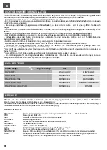
BARRERA IZQUIERDA
Para transformar la barrera de DERECHA a IZQUIERDA efectúe lo siguiente:
1.
Desplace el muelle de la posición derecha a la posición izquierda (Fig. G1)
2.
Invierta los cables del motor en la centralita (35 con 36, página sucesiva)
3.
Invierta los cables 14 con 16 (finales de carrera eléctricos)
Efectuar luego la instalación.
FCS
D
-
TPR.OPEN
FotoRIC.
JOLLY
SLAVE
RIC.AUT.
PRELAMP.
REG.VEL.
P/P
U
S
1
JCC
LD1
RS
P/P
PA
TEST
TR1
FCS
C2
24FT
24V
NA
COM
NC
Slave
LDA
TPR
+
-
P/P
PA
PC
C
CC
STP
FT
CSB
+
-
+
-
-
+
D
M
M
FC1
FC2
C1
ON
CC
STP
FT
TPR
+
-
Reset
A
N
T
.
P3
1
2
3
4
5
6
7
8
9
10
11
12
P/P
STOP
PROG.
SCHEDA RADIO OC
+
1
O
N
+
+
23
1
2
3
4
22
21
20
19
18
5
7
8
13
12 11
14
15
16
9
10
6
17
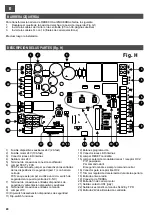
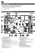
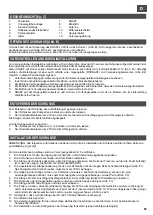
DESCRIPCIÓN DE LAS PARTES (Fig. H)
1)
Fusible dispositivos auxiliares 24V (2A fast)
2)
Fusible motor 24V (10A fast)
3)
Conector luces LED internas
4)
Salida motor 24V
5)
Terminal de conexiones conexión codificador
6)
Jumper TEST y FCS
TEST: sacando este jumper se desactivan las entradas
de los dispositivos de seguridad (part. 7) con barrera
cerrada.
FCS: saque este jumper si utiliza un micro- switch de
seguridad en la puerta (entrada 26 - NC)
7)
Terminal de conexiones entradas dispositivos de
seguridad y alimentación dispositivos auxiliares
8)
Terminal de conexiones entradas comando
9)
Jumper JCC
10) Dip-switch desactivación dispositivos de seguridad
11) Dip-switch funciones
12) Botones programación
13) Conector luces LED internas
14) Jumper RESET centralita
15) Jumper selección modalidad canal 1 receptor OC2:
P/P: paso/paso
PA: comando abrir
El segundo canal es siempre comando cerrar.
16) Conector para receptor tipo OC2
17) Trimmer regulación deceleración durante la apertura
18) Entrada antena radio
19) Conexión de TIERRA
20) Entrada fin de carrera motor
21) Salida contacto US1 (jolly)
22) Salida luces mástil, comandos SLAVE y TPR
23) Entrada 24Vdc alimentación centralita
Fig. H
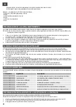
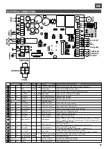
COLLEGAMENTI ELETTRICI
FCS
D
-
TPR
FotoRIC.
JOLLY
SLAVE
RIC.AUT.
PRELAMP.
REG.VEL.
P/P
U
S
1
JCC
LD1
RS
P/P
PA
TEST
TR1
FCS
C2
24FT
24V
NA
COM
NC
Slave
LDA
TPR
+
-
P/P
PA
PC
C
CC
STP
FT
CSB
+
-
+
-
- cable AZUL
+ cable VERDE
D
cable BLANCO
FC1
FC2
C1
ON
CC
STP
FT
TPR
+
-
Reset
A
N
T
.
P3
1
2
3
4
5
6
7
8
9
10
11
12
P/P
STOP
PROG.
SCHEDA RADIO OC
+
1
O
N
+
+
24
V
d
c
M
O
TO
RE
M
1
2
3
4
5
6
7
8
9
1
0
1
1
1
2
1
3
1
5
1
4
1
6
1
7
1
8
1
9
2
0
2
1
2
2
2
3
2
4
2
5
2
6
2
7
2
8
2
9
3
0
3
1
3
2
3
3
3
4
3
5
3
6
EN
CO
DE
R
+
-
+
-
le
d
m
ás
til
sa
lid
a U
S
1
8A
2
30
V
C2
FC1
FC2
C1
1
3
1
5
1
4
1
6
Fin de
carrera
cierre
apertura
FT
STOP
Banda en cierre
Contacto puerta
Botón CERRAR
Botón ABRIR
Botón P/P
Alimentazione
fotocellule
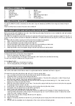
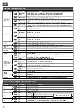
Borne n.
1
5
7
9
10
10
11
12
13
14
15
16
17
18
19
22
20
22
21
23
27
24
27
25
27
26
27
28
29
30
31
32, 33, 34
35
36
TPR
comando SLAVE
Luces MÁSTIL
Salida US1
Salida US1
TIERRA
Contacto NC
Contacto NC
Antena Radio
Botón NA
Botón NA
Botón NA
Banda 8K2 / N.C.
Botón NC
Contacto NC
Contacto NC
Dispositivos auxiliares
Dispositivos auxiliares
Encoder
Motor
24Vdc
24Vac
24V
100 mA
Alimentación Centralita
Ausencia línea
salida comandos SLAVE
Iluminación MÁSTIL
Salida jolly NC
Salida jolly NA
Contatto di TERRA
Finecorsa APRE
Finecorsa CHIUDE
17 Cable de masa,
18 Unidad central
Comando Paso/Paso
Comando Cerrar.
Comando Abrir
Banda en Cierre
Comando Stop
Fotocélula en cierre
Contacto puerta
Alimentación fotocélulas
Alimentación
32 - / 33 + / 34 D
Salida Motor 24V
Dispositivo
V
I máx
Función
Notas
Conectar al secundario del transformador
Conectar en la salida alimentación desde la caja alimentador
conectar a la centralita de la segunda barrera (SLAVE)
Conectar a las luces LED del mástil, si disponibles
Fin de carrera cerca de la apertura
Fin de carrera cerca del cierre
Conectar una antena para 433 MHz (50 ohm)
Véase tabla de configuración dip-switch
Pone en marcha la apertura de la barrera
Pone en marcha el cierre de la barrera
Entrada activa en cierre. Posibilidad de conectar bandas 8K2 (JCC
cerrado) o un contacto N.C. (JCC abierto). Si no se utiliza, abra JCC
y sitúe en ON dip-switch CC (dip 3 de part. 10)
Bloqueo de todas las funciones.
Se non utilizzato, portare in ON il dip-switch STP (dip 2 di part. 10)
Durante el cierre invierte el funcionamiento.
Si no se utiliza, sitúe a on el dip-switch FT (dip 1 de part. 10)
Conecte esta entrada al micro-switch de seguridad de la puerta.
Si no se utiliza, efectúe un puente de conexión en la entrada (cable entre 26 y 27)
Tensión presente sólo cuando la barrera no está cerrada
Tensión permanente
Conexión al Motor
2
3
4
6
8
22
24Vdc
1A max
24Vdc
1
A
m
a
x
.
Datos de contacto: 8A 230V
Datos de contacto: 8A 230V
10 A
32 AZUL, 33 VERDE, 34 BLANCO
A
n
te
n
a
Содержание RAPPER4TL
Страница 4: ...I F E GB D NL 270 Fig D min 200 mm 310 240 m in 400 227 160 min 350 Fig E1 Fig E2 4...
Страница 5: ...I F E GB D NL Fig F Fig G 4 5...
Страница 54: ...NOTE...
Страница 55: ......


