background image

Getting acquainted with the oscilloscope

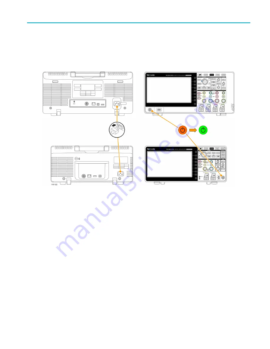
Powering on and off the oscilloscope

Grounding the oscilloscope is necessary for safety and to take accurate measurements. The oscilloscope must share the
same ground as any circuits that you are testing. You connect the oscilloscope to ground by plugging the three-pronged
power cord into an outlet grounded to earth ground.

To connect the power cord and power on the oscilloscope:

To power off the oscilloscope and remove the power cord:

TBS2000 Series User Manual

7

Содержание TBS2072

Страница 1: ...x TBS2000 Series Oscilloscopes ZZZ User Manual P077114701 077 1147 01 ...

Страница 2: ......

Страница 3: ...TBS2000 Series Oscilloscopes ZZZ User Manual xx Revision C Register now Click the following link to protect your product www tek com register www tek com 077 1147 01 ...

Страница 4: ...sedes that in all previously published material Specifications and price change privileges reserved TEKTRONIX and TEK are registered trademarks of Tektronix Inc TekVPI is a registered trademark of Tektronix Inc TekSecure and TekSmartLab are trademarks of Tektronix Inc Contacting Tektronix Tektronix Inc 14150 SW Karl Braun Drive P O Box 500 Beaverton OR 97077 USA For product information sales servi...

Страница 5: ...center is located Customer shall be responsible for paying all shipping charges duties taxes and any other charges for products returned to any other locations This warranty shall not apply to any defect failure or damage caused by improper use or improper or inadequate maintenance and care Tektronix shall not be obligated to furnish service under this warranty a to repair damage resulting from at...

Страница 6: ...charges duties taxes and any other charges for products returned to any other locations This warranty shall not apply to any defect failure or damage caused by improper use or improper or inadequate maintenance and care Tektronix shall not be obligated to furnish service under this warranty a to repair damage resulting from attempts by personnel other than Tektronix representatives to install repa...

Страница 7: ...ensation SPC 20 Getting on screen help for settings Help Everywhere 21 The Scope Intro function 23 Sampling oscilloscope concepts 24 Sampling and acquisition concepts 24 Trigger concepts 26 Trigger slope and level concepts 27 Setting channel input parameters 30 Setting input signal coupling 30 Inverting the input signal 30 Setting the oscilloscope bandwidth 31 Setting the probe type voltage or cur...

Страница 8: ...ents 50 Automatic measurements tip 51 Taking a measurements snapshot 51 Snapshot measurement tip 51 Automatic measurement descriptions 52 Frequency measurement descriptions 52 Time measurement descriptions 52 Amplitude measurement descriptions 53 Area measurement descriptions 55 Taking a measurement on just a part of the waveform Gating 55 Using cursors to take manual measurements 56 Creating math...

Страница 9: ...bling the USB Device port 81 Viewing the USBTMC information 81 Setting up the LAN network 82 Viewing the IP address Ethernet 82 Setting the IP address DHCP network Ethernet 83 Setting the IP address nonDHCP network Ethernet 83 Turning Ethernet DHCP on or off 84 Setting up the Wi Fi network 85 Turning Wi Fi on or off 85 Viewing Wi Fi settings 86 Viewing and selecting available Wi Fi networks 86 Set...

Страница 10: ...graphical user interface elements 106 Warranted specifications 111 The default oscilloscope settings Default Setup 112 Oscilloscope settings that are not reset by Default Setup 113 Physically securing the oscilloscope 114 Environmental considerations 115 Product end of life handling 115 Safety and compliance information 116 Index iv TBS2000 Series User Manual ...

Страница 11: ...component manuals for warnings and cautions related to operating the system When incorporating this equipment into a system the safety of that system is the responsibility of the assembler of the system To avoid fire or personal injury Use proper power cord Use only the power cord specified for this product and certified for the country of use Do not use the provided power cord for other products ...

Страница 12: ...ator shows Examine the exterior of the product before you use it Look for cracks or missing pieces Use only specified replacement parts Do not operate in wet damp conditions Be aware that condensation may occur if a unit is moved from a cold to a warm environment Do not operate in an explosive atmosphere Keep product surfaces clean and dry Remove the input signals before you clean the product Prov...

Страница 13: ... only Do not connect a current probe to any wire that carries voltages above the current probe voltage rating Inspect the probe and accessories Before each use inspect probe and accessories for damage cuts tears or defects in the probe body accessories or cable jacket Do not use if damaged Service safety summary The Service safety summary section contains additional information required to safely ...

Страница 14: ... appear on the product DANGER indicates an injury hazard immediately accessible as you read the marking WARNING indicates an injury hazard not immediately accessible as you read the marking CAUTION indicates a hazard to property including the product When this symbol is marked on the product be sure to consult the manual to find out the nature of the potential hazards and any actions which have to...

Страница 15: ...d Ethernet for remote operation and programming Embedded LXI Web site accessed by typing instrument IP address into a Web browser provides remote UI control and SCPI command support USB 2 0 Host ports for quick and easy storage of screen images instrument settings and waveforms to USB flash drives installing firmware updates and loading waveforms and settings from saved files USB 2 0 Device port f...

Страница 16: ...product DANGER indicates an injury hazard immediately accessible as you read the marking WARNING indicates an injury hazard not immediately accessible as you read the marking CAUTION indicates a hazard to property including the product When this symbol is marked on the product be sure to consult the manual to find out the nature of the potential hazards and any actions which have to be taken to av...

Страница 17: ...Preface Conventions used in this manual The following icons are used throughout this manual Sequence Step Front panel power Connect power Network USB TBS2000 Series User Manual xi ...

Страница 18: ...Preface xii TBS2000 Series User Manual ...

Страница 19: ... the User Manual Programmer Manual and Technical References 063 4568 xx Calibration certificate documenting traceability to national metrology institute s and ISO9001 quality system registration 2 Ch Models Two TPP0100 100 MHz 10X passive voltage probes with 10 MΩ input resistance Probes all models 4 Ch Models Four TPP0100 100 MHz 10X passive voltage probes with 10 MΩ input resistance TPP0100 Five...

Страница 20: ...ption L1 Italian Option L2 German Option L3 Spanish Option L4 Japanese Option L5 Portuguese Option L6 Simplified Chinese Option L7 Traditional Chinese Option L8 Korean Option L9 Front panel overlays are provided with the ordered language option Russian Option L10 2 TBS2000 Series User Manual ...

Страница 21: ...cilloscopes ACD4000B Hard transit case requires use of soft transit case Two and four channel oscilloscopes HCTEK4321 The TBS2000 series oscilloscopes work with multiple optional probes See page 13 Connecting probes to the oscilloscope Check the Tektronix Web site www tek com for the most current information Related documentation Accessory Description Tektronix part number English 077 1147 xx Fren...

Страница 22: ...l of the oscilloscope Available electronically on the Documentation Browser CD or for download from www tektronix com manuals English only 077 1149 xx TBS2000 Series Oscilloscopes Service Manual Service information Available electronically on the Documentation Browser CD or for download from www tek com downloads English only 077 1150 xx 4 TBS2000 Series User Manual ...

Страница 23: ... humidity RH up to 30 C 5 to 60 RH above 30 C up to 50 C noncondensing Operating altitude Up to 3000 meters 9842 feet Power requirements Characteristic Description Power source voltage 100 VAC 240 VAC 10 RMS single phase Power source frequency 50 60 Hz over entire source voltage range 400 Hz 360 Hz to 440 Hz for 115 VAC 100 VAC 132 VAC RMS source voltage range Power consumption All models 80 W max...

Страница 24: ...ith the oscilloscope This section shows you how to power on the oscilloscope and uses a hands on approach to introduce you to key oscilloscope functions using the menu system and verifying that the oscilloscope is operating correctly 6 TBS2000 Series User Manual ...

Страница 25: ...easurements The oscilloscope must share the same ground as any circuits that you are testing You connect the oscilloscope to ground by plugging the three pronged power cord into an outlet grounded to earth ground To connect the power cord and power on the oscilloscope To power off the oscilloscope and remove the power cord TBS2000 Series User Manual 7 ...

Страница 26: ...guage You can change the language used for the oscilloscope on screen display measurements readouts and menus to one of 11 languages The following steps show how to change the user interface language These steps also introduce you to the oscilloscope menu system 1 Push the Utility front panel button The oscilloscope displays a side menu on the right side of the screen 2 Push the Language side menu...

Страница 27: ... Multipurpose knob to select and click values in that item The turn arrow indicator located below the knob turns green when you can use the knob to make selections or enter values in a menu or dialog box The knob has two functions Select function where you turn the knob to select highlight a menu item Selecting a menu item does not execute run that function Click function where you push the knob t...

Страница 28: ...If you load a language other than English install the plastic overlay on the front panel to provide labels in that language Fold the overlay tabs Push the overlay over the knobs until the knob hole tabs click over the bottom edges of the knobs Insert the overlay tabs into the small slots If you are changing from a non English language to English remove the front panel language overlay 10 TBS2000 S...

Страница 29: ...k NOTE The clock does not automatically adjust for seasonal time changes The calendar does adjust for leap years The following steps show how to set the oscilloscope clock with the current date and time These steps also introduce you to more functions of the menu system 1 Push Utility front panel button 2 Push Set Date Time side menu button The oscilloscope shows the Set Date Time menu 3 Turn the ...

Страница 30: ... to menu select mode 6 Repeat steps 3 5 to select and change the remaining date and time settings Month Day Hour Minute 7 When you have finished making all date and time changes turn the Multipurpose knob to select Set Date Time then click the knob to enter the date time settings into the oscilloscope 8 To turn off displaying the date and time select Display Date Time and click the Multipurpose kn...

Страница 31: ... base into the channel connector until the probe base connector clicks To remove push and hold the button on the probe base and pull the probe from the connector TekVPI probes automatically set the oscilloscope probe parameters such as type voltage current and attenuation 10X 1X X10 and so on Supported probe types For more information on the many probes available for use with TBS2000 Series oscill...

Страница 32: ... the oscilloscope 3 Connect a probe that came with the oscilloscope to channel 1 4 Connect the probe tip and ground lead to the PROBE COMP connectors on the oscilloscope front panel The probe tip connects to the 5 V connector and the ground clip connects to the ground connector 5 Push Default Setup Default Setup returns the oscilloscope settings to factory default values See page 112 The default o...

Страница 33: ...wave If the displayed square wave tops are not flat perform the procedures to compensate the probe high frequency response You can compensate the probe after completing this functional check See page 17 7 Push Measure to open the Measurement Selection menu TBS2000 Series User Manual 15 ...

Страница 34: ...apshot screen Push the Menu On Off button again to close the Measurement screen What is Autoset The functional check used the Autoset button to display a stable waveform Autoset automatically adjusts the oscilloscope acquisition horizontal trigger and vertical controls to display five or six waveform cycles for an active displayed channel This powerful function can save you time when you need to v...

Страница 35: ... on the leading edge means that the high frequency response is too high and must be reduced A square leading edge means that the frequency response is correct for the probe Whenever you attach a passive voltage probe for the first time to any input channel or change a passive probe from one channel to another you must compensate the probe to match it to that input channel To properly compensate yo...

Страница 36: ...th the oscilloscope 4 Push Default Setup 5 Push the Vertical Menu button for the channel to which the probe is connected to display that channel 6 Push Autoset The screen displays a square wave 18 TBS2000 Series User Manual ...

Страница 37: ... a flat top and bottom to the waveform Remove the adjustment tool before looking at the waveform Repeat until waveform top and bottom are flat 9 Repeat this procedure from step 5 for each probe connected to each channel You must also run this procedure if you move a probe from one channel to another Probes and ground leads tip When taking a real measurement use the shortest possible ground lead an...

Страница 38: ...t 20 minutes 2 IMPORTANT Remove all input signals probes and cables from channel inputs and the Aux Out connector on the back of the oscilloscope 3 Push Utility 4 Push the More Page 1 2 side menu button 5 Push the Calibration side menu button 6 Turn the Multipurpose knob to select Signal Path then click the Multipurpose knob to start the SPC process The oscilloscope shows a Signal Path Compensatio...

Страница 39: ... you are first learning the functions of oscilloscope controls You can enable Help Everywhere content for all supported settings or enable it for specific function groups such as Trigger controls Vertical controls and so on 1 Push the Function front panel button 2 Push the Help Everywhere side menu button to display the menu All Help Everywhere content is set to Off by default except for the Measu...

Страница 40: ...se knob to select a category then click the knob to toggle that selection On or Off The next time you access a Help Everywhere supported menu setting the oscilloscope displays the help for that item NOTE You may need to turn the Multipurpose knob and select another menu item to show the Help Everywhere content When any Help Everywhere content is enabled the Help Everywhere icon is highlighted in u...

Страница 41: ...pose knob to select and click a topic heading 4 Use the Multipurpose knob to select and click a topic to read 5 Push the relevant side menu button to return to the menu for the subject category and select and click the next topic to view 6 When you are done viewing the topics for that category push the Scope Intro side menu button to return to the main menu and select a new category to read 7 Push...

Страница 42: ...hen one channel per channel pair is active channel 1 2 pair or channel 3 4 pair For two channel models only one channel either channel 1 or 2 can sample at 1 Gs s If channel 1 and 2 are both active then the maximum sample rate changes to 500 MS s On four channel models only two channels can sample at 1 GS s one channel from each pair So if channel 1 or 2 and channel 3 or 4 are active the maximum s...

Страница 43: ...hest and lowest of all the samples contained in two consecutive acquisition intervals Use this mode to help detect short rapid transitions in a waveform Peak Detect is not available at faster time per division settings Hi Res mode oversamples lower frequency signals and calculates the average of all the samples for each acquisition interval Use Hi Res mode to provide higher resolution 16 bit sampl...

Страница 44: ...e level on the rising edge of the signal The oscilloscope uses that trigger condition to store the waveform samples in the waveform record so that the signal sample point that meets the trigger condition is at the same location in the waveform record When displayed the waveform record for each acquisition shows the waveform at the same trigger point resulting in a stable waveform on the screen Tri...

Страница 45: ... edge of a signal The level sets where on that edge the trigger point occurs The trigger Slope sets the oscilloscope to find the trigger event on the rising or the falling edge of a signal The trigger threshold Level or just level is the signal amplitude value on a slope that must occur for the oscilloscope to trigger on a signal A runt trigger needs two thresholds to define the two levels that a ...

Страница 46: ...r coupling sets what part of the input signal is used by the trigger circuit Trigger coupling choices are DC LF Reject HF Reject and Noise Reject DC Coupling passes the trigger signal to the trigger circuit with no filtering The scope may trigger on false events if the signal is noisy HF Reject blocks signals above 85 kHz from the trigger circuit This reduces false triggering on high frequency noi...

Страница 47: ...events the oscilloscope from triggering on any positive signal edge Use Set Holdoff to minimum to set the holdoff value to the minimum value NOTE The trigger mode does not set the trigger conditions those are set with the trigger Type controls See page 27 Available trigger types Trigger delay acquisition mode In normal acquisition modes the trigger point is located at the center of the waveform re...

Страница 48: ...he coupling type DC coupling passes both AC and DC signal components AC coupling blocks the DC component and passes only the AC signal Ground internally disconnects the input signal and connects that channel to a ground reference This is a fast way to determine where the ground level is for signals that have a DC component or offset Inverting the input signal Use this procedure to invert flip vert...

Страница 49: ...width setting Full sets the bandwidth to the maximum bandwidth of which the oscilloscope is capable 20 MHz sets the bandwidth to 20 MHz Other bandwidth choices may be shown on the menu depending on the connected probe Setting the probe type voltage or current The Probe Type submenu sets the type for probe that is connected to the oscilloscope The default probe type is Voltage The other valid probe...

Страница 50: ... Set To 10X submenu items let you quickly set the probe attenuation to either 1X or 10X 1 Push the Vertical Menu button for the channel input that you want to set 2 Push the Probe Setup side menu to display the Probe Setup submenu 3 Use the Multipurpose knob to highlight either Set To 1X or Set To 10X submenu item Then click the multipurpose knob to set that value Setting the Measure Current mode ...

Страница 51: ...e waveform on the screen moves as you change the value Click the knob again to exit the field 4 To set the offset value to 0 use the Multipurpose knob to select and click Set to 0 Setting the waveform vertical position To quickly position a waveform position use the Vertical Position knob on the front panel for the channel that you want to move The Position submenu lets you set the vertical signal...

Страница 52: ...waveform peak area Setting channel deskew Deskew compensates for differences in signal delays between different cable lengths or probe types Use Deskew to adjust the signal delay for individual channels so that all signals arrive at the oscilloscope at the same time Deskewing channels lets you take accurate time related measurements between two or more channels or when using a current probe with a...

Страница 53: ... Multipurpose knob to select and click Set to Default Deskew tips Deskew settings are stored in nonvolatile memory until changed manually for each channel Deskew settings are included in saved setup files Doing a Default Setup resets deskew values to 0 on all channels TBS2000 Series User Manual 35 ...

Страница 54: ...rigger coupling 6 Push the Slope side menu button to select between rising and falling slope edges on which to trigger the oscilloscope 7 Push the Level side menu button and use the Multipurpose knob to select and click the trigger level entry method Click Level and use the Multipurpose knob to manually set the trigger level Click Choose Preset and use the Multipurpose knob to set the trigger leve...

Страница 55: ...ect AC Line to use the AC power source frequency as the trigger signal 5 Push the Polarity side menu button and use the Multipurpose knob to select and click the pulse polarity positive or negative to trigger on 6 Push the Threshold side menu button and use the Multipurpose knob to select and click the trigger level entry method Click the threshold field and use the Multipurpose knob to manually s...

Страница 56: ...e trigger signal source or select AC Line to use the AC power source frequency as the trigger signal 5 Push the Polarity side menu button and use the Multipurpose knob to select and click the runt pulse polarity positive negative or either to trigger on 6 Push the Thresholds side menu button and use the Multipurpose knob to select and click the trigger levels thresholds to use to detect a runt pul...

Страница 57: ... holdoff mode Click Auto Untriggered Roll to set the oscilloscope to acquire and display a waveform even if a trigger does not occur If there is no valid triggering event the waveform will appear to roll across the screen See page 28 Auto Untriggered Roll trigger mode Click Normal to set the oscilloscope to acquire and display a waveform only when a valid trigger event occurs See page 29 Normal tr...

Страница 58: ...ast Autoset Autoset tips If more than one channel is active Autoset triggers on the lowest numbered displayed channel and displays all active channels from the top to the bottom of the screen Autoset always sets vertical offset to 0 V Channel 1 is a special case If all channels are off not displayed or channel 1 is on Autoset attempts to detect trigger and display the waveform for channel 1 even i...

Страница 59: ...e the Autoset Enable Disable password Autoset requires a password to enable or disable the Autoset mode 1 Push Utility 2 Push More Page 1 2 side menu button 3 Push Autoset Enable side menu button 4 Use the Multipurpose knob to select and click Change Password The oscilloscope opens the Change Password entry screen 5 Use the Multipurpose knob and side menu buttons to select alphanumeric and enter c...

Страница 60: ...Single sets the trigger mode to Normal for the single acquisition Setting the acquisition mode Use the acquisition mode to set how the oscilloscope uses the sampled data points in each acquisition interval to create and display a waveform See page 25 Acquisition mode concepts 1 Push Acquire 2 Push the Mode side menu button 3 Turn the Multipurpose knob to select a mode Sample Peak Detect Hi res Ave...

Страница 61: ...ay from the expansion point center graticule The amount of delay is shown in the Horizontal Status area at the bottom center of the graticule referenced to 0 s center graticule The trigger point can move off the screen when this happens the trigger marker changes to show the direction of the trigger point Trigger point is off screen delay time shown on readout at bottom of the screen 4 Once you ar...

Страница 62: ... samples data points are added to a waveform record Available record lengths are 2000 20 000 200 000 2 million 2M and 20 million 20M points NOTE 20M waveforms cannot be loaded into reference memory either directly from the oscilloscope or from a saved file All other record length waveforms can be loaded into reference memory 1 Push Acquire 2 Push the Record Length side menu button 3 Use the Multip...

Страница 63: ...nt when the trigger mode is Auto and the horizontal scale and record lengths are set as follows Table 1 Roll mode is enabled when Horizontal scale setting Record length number of samples 40 ms div 2000 20k 200k 2M 400 ms div 20M Roll mode tips Push Run Stop to halt Roll mode Role mode is disabled under the following conditions When using Reference Math or FFT waveforms Using the Zoom function Taki...

Страница 64: ...n state before setting up to take a new measurement See page 112 The default oscilloscope settings Default Setup To return the oscilloscope to its factory default settings 1 Push Default Setup 2 If you change your mind push Undo Default Setup side menu button to return the oscilloscope to the settings present before you pushed Default Setup You must push this button before doing any other action 4...

Страница 65: ...ence sets the time for how long the oscilloscope retains and displays the sampled waveform points on the screen Using longer or infinite persistence times helps to display infrequent or random signal anomalies such as glitches Normal persistence sets the oscilloscope to erase the current waveform data as it draws the newest acquisition Changing the persistence time from 1 second to 10 seconds sets...

Страница 66: ...m acquisition The XY display mode The XY display mode plots the signal amplitude of channel 1 X against the amplitude of channel 2 Y where channel 1 is the horizontal axis and channel 2 is the vertical axis XY display mode is useful for showing signal phase or frequency relationships between periodic signals The resulting XY plots are called Lissajou patterns You can display Ch 1 versus Ch 2 On fo...

Страница 67: ...f line analysis Use a Web browser and search on the keyword lissajou patterns to find more information on XY plots Setting the backlight intensity Use this procedure to change the overall screen lighting level Higher settings are better for brightly lighted areas and lower values are better for dimly lighted areas 1 Push Utility 2 Push the Display side menu button 3 Use the Multipurpose knob to se...

Страница 68: ... Push the side menu button to select the channel on which to take measurements 4 Use the Multipurpose knob to select and click a measurement See page 52 Automatic measurement descriptions The Measurement Selection bar at the top of the screen updates to show that a measurement was selected for that channel indicated by color up to a maximum of six measurements total to display 5 Measurements with ...

Страница 69: ... for which to show the measurement snapshot You can only take a snapshot of one channel at a time 4 Use the Multipurpose knob to select and click Snapshot the snapshot screen opens immediately 5 If the File Save button is set to save an image push the File Save button to save the snapshot image to a file See page 70 Saving files to USB with the Save File button 6 Push the Menu On Off button to clo...

Страница 70: ... crossing in the waveform or gated region Pulses The number of negative pulses that fall below the mid reference crossing in the waveform or gated region Edges The number of positive transitions from the low reference value to the high reference value in the waveform or gated region Edges The number of negative transitions from the high reference value to the low reference value in the waveform or...

Страница 71: ...nd waveforms See also Phase This measurement requires inputs from two channels Phase The amount of time that one waveform leads or lags another waveform expressed in degrees where 360 makes up one waveform cycle See also Delay RR RF FR FF This measurement requires inputs from two channels Width Positive pulse width The distance time between the mid reference default 50 amplitude points of a positi...

Страница 72: ...ted region Low This value is used as 0 whenever high reference mid reference or low reference values are needed such as in fall time or rise time measurements Calculated using either the min max or histogram method The min max method uses the minimum value found The histogram method uses the most common value found below the midpoint This value is measured over the entire waveform or gated region ...

Страница 73: ...he common reference point is negative Taking a measurement on just a part of the waveform Gating Gating sets the automatic measurements to use only a specified part of a waveform for the measurements The Gating function applies to all channels and all measurements in other words you cannot set a different gating region for individual measurements or different channels 1 Push Measure 2 Push the Gat...

Страница 74: ...nt cursor positions The readouts also show the difference delta marked with a Δ symbol between the cursor measurements The oscilloscope always shows the readouts when the cursors are turned on NOTE Cursors are not available in XY display mode 1 Push Cursors to display two vertical Time cursors by default The color of the cursors indicates the channel on which they are taking measurements The solid...

Страница 75: ...ton to turn cursor linking On or Off If linking is On turning the Multipurpose knob moves both cursors at the same time 7 If one or both of the cursors are off of the screen push the Bring Cursor On Screen side menu button to bring off screen cursors back to the screen 8 Push the Cursors front panel button to turn the cursors off Cursor types The cursor types are Time or Frequency cursors These ve...

Страница 76: ...rrent side menu settings 2 Push the Source 1 side menu button 3 Use the Multipurpose knob to select and click the first channel to use for the math waveform 4 Push the Operator side menu button 5 Use the Multipurpose knob to select and click the math operation to apply to the two waveforms add subtract or multiply 6 Push the Source 2 side menu button 7 Use the Multipurpose knob to select and click...

Страница 77: ...ignal frequency information There are many signals that have some sort of distortion or unwanted characteristics Sometimes these distortions do not affect how that signal works in the circuit But often system clock pulses signals induced from a nearby printed circuit path or noise from a power supply or other source can affect a signal and prevent it from operating correctly The FFT function is a ...

Страница 78: ...lect and click dBV RMS or Linear RMS Use the default dBV RMS Vertical Units scale to see a detailed view of multiple frequencies even if the frequencies have very different amplitudes Use the Linear RMS vertical scale to see an overall view of how all frequencies levels compare to each other 6 Push the Window side menu button and use the Multipurpose knob to select and click Hanning Rectangular Ha...

Страница 79: ...e vertical size of the FFT waveform Use cursors to measure frequencies and relative signal levels Input signals that have a DC component or offset can cause incorrect FFT waveform component magnitude values To minimize the DC component use AC Coupling on the input signal To reduce random noise and aliased components See page 63 in repetitive or single shot events set the oscilloscope acquisition m...

Страница 80: ... is a good starting point for FFT measurements Table 2 FFT windows Window type Window shape Hanning This is a very good window for measuring amplitude accuracy but less so for resolving frequencies Use Hanning for measuring sine periodic and narrow band random noise This window works on transients or bursts where the signal levels before and after the event are significantly different Rectangular ...

Страница 81: ...e sample rate The frequency components that are above the Nyquist frequency are undersampled and appear to fold back or reflect around the right edge of the graticule showing as lower frequency components in the FFT waveform These incorrect components are called aliases You can use the following methods to reduce or eliminate aliases Increase the sample rate by adjusting the Horizontal Scale front...

Страница 82: ...arn how to save waveforms to reference memory or external files See page 67 Saving waveform data 1 Push the R Ref front panel button 2 Push the Ref1 or Ref2 side menu button to toggle displaying that waveform On or Off You can display both reference waveforms at the same time Reference waveform tips You cannot position or scale a reference waveform You should set the source waveform position and s...

Страница 83: ... the position and size of the zoomed part in the waveform in brackets within the entire record The lower display shows the zoomed view of the waveform the part enclosed in brackets in the upper display 1 Select the channel that you want to zoom 2 Push Zoom 3 Push the Scale side menu button and use the Multipurpose knob to adjust the size of the area to zoom magnify 4 Push the Position side menu bu...

Страница 84: ...further analysis whereas you can load the data from a waveform file into other oscilloscopes or into PC based analysis programs to perform advanced signal measurements 1 Install a USB drive 2 Set up the display to show the waveforms and other readouts that you want to save 3 Push the Save Recall front panel button 4 Push the Action side menu button 5 Use the Multipurpose knob to select and click S...

Страница 85: ...veform data to a reference Ref memory location or an external file 1 Optional Install a USB drive to save the waveform data to a file on the USB drive 2 Acquire and display the waveform that you want to save 3 Push the Save Recall front panel button 4 Push the Action side menu button 5 Use the Multipurpose knob to select and click Save Waveform 6 To save waveform data to internal reference memory ...

Страница 86: ...omatically generated file names About waveform data files ISF Internal File Format Sets the oscilloscope to save waveform data from analog channels and math and reference waveforms derived from analog channels in internal waveform save file ISF format This format is the fastest to write and creates the smallest sized file Use this format if you intend to recall a waveform to reference memory for v...

Страница 87: ... USB drive to save the setup data to a file on the USB drive 2 Push the Save Recall front panel button 3 Push the Action side menu button 4 Use the Multipurpose knob to select and click Save Setup 5 To save setup data to internal setup memory a Push Save To side menu button b Select and click Setup c Push Setup side menu button and use the Multipurpose knob to select the setup memory location 1 10...

Страница 88: ...ault file save location on the USB drive Files are saved to the USB drive using a specific naming convention See page 78 About automatically generated file names 1 Push the Save Recall front panel button 2 Push the Assign To side menu button 3 Push the side menu buttons for the action that you want to assign to the Save button Screen Image Waveform or Setup The save button is now assigned to that ...

Страница 89: ...uration 1 Optional Install a USB drive to recall the setup data from a file on the USB drive 2 Push the Save Recall front panel button 3 Push the Action side menu button 4 Use the Multipurpose knob to select and click Recall Setup 5 To recall setup data from internal setup memory a Push the Recall From side menu button b Select and click Setup c Push the Setup side menu button and use the Multipur...

Страница 90: ...rence memory 1 Install a USB drive that contains the ISF waveform data file 2 Push the Save Recall front panel button 3 Push the Action side menu button 4 Use the Multipurpose knob to select and click Recall Waveform 5 Push the To side menu button 6 Select and click Ref1 or Ref2 7 Push Select File side menu button to open the File Utility pane 8 Use the Multipurpose knob to select the waveform fil...

Страница 91: ... File Utility pane To open the File Utility pane push the Save Recall front panel button and push the File Utility side menu button The Directory field lists the path for the highlighted folder or file This is also the field you use to enter text to create or rename files or folders The area below the Directory field shows the files and folders Use the Multipurpose knob to highlight a name Push th...

Страница 92: ...tire name NOTE If you are renaming an image waveform or setting file you do not need to add the extension name when renaming the file Use the upper side menu buttons to delete the character to the left of the cursor Backspace or move the cursor left or right in the Directory field Use the lower side menu buttons to show upper or lower case letters on the keyboard or show a numeric keypad Push the ...

Страница 93: ...aved files will now be saved to this location Default save folder location rules The new save folder location remains in effect until A new location is set with the Change Folder button The oscilloscope is powered down The save location changes back to the top level of the USB drive The following actions do not change the file save location The oscilloscope shows an error message when it tries to ...

Страница 94: ... enter are shown at the top of the file pane 6 Repeat step 5 until you have entered the folder name 7 Push the OK side menu button to add the new folder name to the USB drive NOTE There are four names at the top of the character list default values are MyProject1 4 These names will change to show the most recent file or folder names that you have created These names change back to the default valu...

Страница 95: ... USB drive 1 Push the Save Recall front panel button 2 Push the File Utility side menu button 3 Use the Multipurpose knob to navigate to the location at which to create the new folder 4 Push the Rename side menu button 5 Select and click a recently created name listed at top of the characters list or enter the folder or file name using the Multipurpose knob and side menu buttons to scroll through ...

Страница 96: ... or JPG for screen image files SET for setup files ISF or CSV for waveform files To create a new file name the oscilloscope scans the USB drive to determine the highest numbered file name present for the file type being saved The oscilloscope then increments that number and uses it for the new file name For example the first time you save a file the oscilloscope creates the file name TEK00000 The ...

Страница 97: ...ence memories with zero 0 values Replaces the current front panel setup and all stored setups with the default setup Displays a confirmation or warning message depending on whether the verification is successful or unsuccessful 1 Push Utility 2 Push the Config side menu 3 Use the Multipurpose knob to select and click TekSecure Erase Memory 4 The screen shows a confirmation message 5 Select and cli...

Страница 98: ...d to the USB Device port A supported device does not need to be connected to the USB Device port to select that item NOTE The current software release only supports a PC connection 1 Push Utility front panel button 2 Push the Config side menu button The USB menu item at top of the Config side menu shows the USB Device port connection status 3 Use the Multipurpose knob to select and click USB The U...

Страница 99: ...ct and click USB 4 Select and click Disabled Off Bus Viewing the USBTMC information USBTMC stands for USB Test Measurement Class USBTMC is a protocol that allows USB devices to communicate using IEEE488 style messages This protocol lets you run your GPIB software applications on USB hardware Use this screen to view protocol registration information There are no active controls on this screen 1 Pus...

Страница 100: ...ork Viewing the IP address Ethernet Use this procedure to see the oscilloscope IP address and related network settings You may need the IP address information to make a connection to the oscilloscope from a PC running on the network 1 Push Utility front panel button 2 Push the Config side menu button 3 Use the Multipurpose knob to select and click Ethernet Config 4 Select and click LAN Settings Th...

Страница 101: ...urpose knob to select and click Ethernet Config 4 Highlight DHCP 5 Push the Multipurpose knob to select ON The oscilloscope takes a few moments to request and load the IP address from the DHCP server The LAN Test menu items should now show OK and the network connection icon upper right edge of screen should be on white 6 You can find out the IP address that was loaded into the oscilloscope See pag...

Страница 102: ...ur system administrator to confirm that the settings that you were given are correct Check that you entered the settings correctly Turning Ethernet DHCP on or off A Dynamic Host Configuration Protocol DHCP network automatically allocates network IP addresses and settings to DHCP enabled instruments like the TBS2000 Series oscilloscope Use this procedure to turn the oscilloscope DHCP capability on ...

Страница 103: ...ion before you can communicate with the oscilloscope Use this procedure to turn on or off Wi Fi Prerequisites Connect a supported Wi Fi dongle to the rear USB Host port Tektronix option TEKUSBWIFI Recommendation is to use the rear USB port so that you keep the front USB port available for saving and loading files DHCP connectivity is On 1 Push the Utility front panel button 2 Push the Config side ...

Страница 104: ...electing available Wi Fi networks Use this procedure to see the Wi Fi networks the oscilloscope can detect and select the Wi Fi network to use for communication Prerequisite A Wi Fi dongle is connected to the oscilloscope and Wi Fi is turned on See page 85 Turning Wi Fi on or off 1 Push the Utility front panel button 2 Push the Config side menu button 3 Use the Multipurpose knob to select and clic...

Страница 105: ...in a permanent IP address and then add it manually to the oscilloscope Prerequisites A supported Wi Fi dongle is connected to the oscilloscope and Wi Fi is turned on See page 85 Turning Wi Fi on or off The oscilloscope must be connected to a DHCP enabled network 1 Push Utility front panel button 2 Push the Config side menu button 3 Use the Multipurpose knob to select and click Wi Fi Config 4 Highl...

Страница 106: ...rned on See page 85 Turning Wi Fi on or off Obtain the correct network settings from your system administrator IP address Subnet Mask and Default Gateway 1 Push Utility front panel button 2 Push the Config side menu button 3 Use the Multipurpose knob to select and click Wi Fi Config 4 Select and click IP Addresses Settings The oscilloscope opens the IP Addresses Settings dialog box 5 Use the Multi...

Страница 107: ...s turned on See page 85 Turning Wi Fi on or off The network to which you are connecting must be DHCP enabled 1 Push Utility front panel button 2 Push the Config side menu button 3 Use the Multipurpose knob to select and click Wi Fi Config 4 Highlight DHCP 5 Push the Multipurpose knob to select ON The oscilloscope takes a few moments to request and load the IP address form the DHCP server The LAN T...

Страница 108: ...ting up the LAN network See page 85 Setting up the Wi Fi network 1 Open a Web browser on the PC 2 Enter the oscilloscope IP address on the URL line of the browser For example HTTP 135 62 88 157 3 The browser searches for and opens the TBS2000 Welcome Web page for the oscilloscope NOTE If the PC browser does not display the oscilloscope browser page verify that the oscilloscope is connected and com...

Страница 109: ... shows Update Firmware message 7 Turn the Multipurpose knob to select Yes then click the Multipurpose knob to install the firmware 8 Follow the on screen instructions NOTE Do not power off the oscilloscope or remove the USB flash drive until the oscilloscope finishes installing the firmware It displays a message saying it is OK to turn off the oscilloscope 10 When the firmware install is finished ...

Страница 110: ...st side menu button to display the Self Test menu and Self Test Results readout 5 Turn the Multipurpose knob to select Run Self Test then click the Multipurpose knob to start testing using the default settings the self test takes a few seconds to run 6 Use the other Self Test menu items to refine how to run the self test you can run the tests a specified number of times Loop Times run tests foreve...

Страница 111: ... or a communication box to connect to the TekSmartLab server See the Scope Intro topic on TekSmartLab for more information Function Scope Intro TekSmartLab You can also go to the Courseware Web page at www tek com courseware to download courseware files that others have created and uploaded to share NOTE Courseware files are compressed using zip format Unzip the Courseware file and copy the uncomp...

Страница 112: ... to this location for reading the courseware files The selected folder is highlighted in the list 7 Push the Upload Course side menu button to load the course into your oscilloscope The oscilloscope displays a brief message saying that the file loaded successfully Dealing with No course material package files found error message If you get the No course material package files found error message m...

Страница 113: ... button push the Step side menu button use the Multipurpose knob to select the step number and push the Show Reference side menu button to On The oscilloscope shows the reference material associated with that step If a step says to show a waveform mask push the Data Collection side menu button push the Step side menu button use the Multipurpose knob to select the step number and push the WFM Mask ...

Страница 114: ...If the report has any errors or is missing information push the Back side menu button and redo the step or steps that are missing information and rerun the Report procedure 3 If the report is OK push the Save side menu button The oscilloscope saves the report to the USB drive 4 To confirm the report was written push Save Recall side menu button push File Utility side menu button search for and ope...

Страница 115: ...menu or other choices to move a cursor and to set a numerical parameter values for a menu item A blue M icon on a menu message or dialog box means to use the Multipurpose knob to interact with that item The arrow symbol below the knob will also light up when you can use the knob to control screen objects or interact with menu items Turn the knob to highlight a menu item or control a screen object ...

Страница 116: ...ical and horizontal Position knobs vertical Scale knob and the trigger Level knob The Zoom button displays a magnified waveform See page 65 How to view long record length waveforms Zoom 1 The Search and Mark buttons Previous Next and Set Clear and theMultipurpose knob let you add marks tags to points on a signal of interest waveform and quickly jump to those marks This is very useful when examinin...

Страница 117: ...length The Horizontal Scale knob adjusts the horizontal time base scale time per horizontal graticule division and samples per second The Trigger controls The Trigger controls set when the oscilloscope starts acquiring signal data to create a waveform record See page 26 Trigger concepts See page 36 Trigger setup The Trigger Menu button opens the side menu for trigger settings The Trigger Level kno...

Страница 118: ...emove that channel s waveform from the display See page 30 Setting channel input parameters See page 47 Displaying and removing a waveform The Vertical Scale knob sets the vertical scale volts or units per vertical graticule division for each channel NOTE Push the Fine button in Navigation controls to let you make smaller adjustments with the knob The M Math button opens the side menu where you ca...

Страница 119: ...s controls to access and manage files on a connected USB drive See page 73 Using the USB File Utility functions Other front panel controls The Courseware graduation cap button opens a side menu where you can access the Tektronix Courseware lab exercise functions See page 93 Courseware on instrument education and training The Function button opens a side menu where you can select optional analysis ...

Страница 120: ...nu system 1 Push a front panel menu button to display the menu that you want to use The oscilloscope opens the side menu list for that button on the right side of the screen 2 Push a side menu button to select the on screen menu item that is next to that button 102 TBS2000 Series User Manual ...

Страница 121: ... value to complete the setup Use the Multipurpose knob and side menu buttons to highlight select and adjust those settings 7 Push Fine to turn off or on the ability to make smaller adjustments with the Multipurpose knob Fine works with the Multipurpose knob Horizontal and Vertical Position knobs Vertical Scale knob and the Trigger Level knob The following topics provide hands on experience with us...

Страница 122: ...satile Probe Interface 2 PROBE COMP A square wave signal source and ground connection used to compensate probes Output voltage 5 V at 1 kHz Ground reference to which to connect the probe ground lead See page 17 Compensating a passive voltage probe 3 USB 2 0 Host port 104 TBS2000 Series User Manual ...

Страница 123: ...10 100 Base T local area network for file or printer access 3 USB 2 0 Host port A standard USB host port which lets you connect a USB Wi Fi transceiver adapter dongle for wireless connectivity A Tektronix TBS2000 series exclusive feature or to USB flash drives with which to save or recall waveforms settings screen images and Courseware education packages 4 USB 2 0 Device port Use the USB 2 0 Full ...

Страница 124: ...scope is 40 ms per division or slower time base setting and the signal is shown as a slow scrolling waveform moving from right to left PreVu The oscilloscope is stopped and you have used the Horizontal or Vertical Scale or Position knobs to change setting s In PreVu mode the oscilloscope is showing a preview of what the next acquisition might look like with the changed position or scale settings b...

Страница 125: ... triangle at the top of the T shows the center point around which the horizontal scale control expands or shrinks the waveform the center expansion point 4 The waveform record view shows the trigger location relative to the entire waveform record The line color corresponds to the selected waveform color The area in brackets is the part of the waveform record that is displayed on the screen 5 The W...

Страница 126: ...n in runt trigger mode Use the Trigger Menu to set both trigger levels 10 The Time and Date readout shows the oscilloscope clock setting See page 11 Changing the date and time 11 The Horizontal and Trigger readouts show Trigger horizontal scale sample rate trigger delay time and record length information The Trigger readouts shows the trigger source slope and the trigger threshold level The readou...

Страница 127: ...surement units per major vertical graticule division input signal coupling signal invert status and the oscilloscope bandwidth setting Adjust these settings by using the Vertical Scale knob and the channel 1 2 3 or 4 menus 13 The measurement readouts show the selected measurements You can select up to six measurements to display at one time See page 50 Taking automatic measurements Push the Menu O...

Страница 128: ...s 14 The waveform baseline indicator left side of the screen shows the zero volt level of a waveform The icon colors correspond to the waveform colors Adjust waveform position with the Vertical Position knob 110 TBS2000 Series User Manual ...

Страница 129: ...erformance Verification Technical Reference Manual Tektronix part number 077 1148 xx for the warranted specifications and performance verification procedure This manual is English only and can be downloaded from the Tektronix Web site www tek com downloads TBS2000 Series User Manual 111 ...

Страница 130: ...Ch1 Display Persist Auto Mode YT Backlight 80 Graticule On FFT Source wfm On Vertical Units dBv RMS Window Hanning Horizontal Scale time per major horizontal division 4 00 μs div Delay On Trigger position 0 00 s Math waveform Source 1 Ch1 Source 2 Ch2 Operation add Measurements Source Ch1 Selected measurements None Trigger Type Edge Source Ch1 Coupling DC Slope Rising Level 0 00 V Mode Auto USB De...

Страница 131: ...Default Setup button does not reset or change the following settings Language option Date and time Saved setups in memory Saved reference waveforms in memory Calibration data Network Wi Fi settings Probe setup type and attenuation factor Current save folder on the USB flash drive TBS2000 Series User Manual 113 ...

Страница 132: ...Physically securing the oscilloscope Physically securing the oscilloscope Use a standard laptop security lock cable to attach your oscilloscope to your location 114 TBS2000 Series User Manual ...

Страница 133: ... if improperly handled at the product s end of life To avoid release of such substances into the environment and to reduce the use of natural resources we encourage you to recycle this product in an appropriate system that will ensure that most of the materials are reused or recycled appropriately This symbol indicates that this product complies with the applicable European Union requirements acco...

Страница 134: ...ation Safety and compliance information See the TBS2000 Series Safety and Installation Instructions document for product safety and emissions compliance information Tektronix part number 071 3445 xx 116 TBS2000 Series User Manual ...

Страница 135: ...enu 100 Courseware 101 Cursors 98 Default Setup 101 F FFT 100 Fine 98 Force Trig 99 Function 101 M Math 100 Mark 98 Measure 101 Menu On Off 101 R Ref 100 Run Stop 101 Save Recall 101 Search 98 Set Clear 98 Single 101 Trigger Menu 99 Utility 101 Zoom 98 C Cable impedance adapter 13 Calibration 20 Calibration certificate 1 Carry case hard 3 Carry case soft 3 Change file save location USB 75 Change F...

Страница 136: ...ayRF measurement 53 DelayRR measurement 53 Deleting files or folders USB drive 76 Deskew pulse generator and signal source 3 Deskew setting 34 Determining channel of saved ISF file 78 DHCP IP address 83 DHCP on off 84 DHCP on off Wi Fi 89 Difference between offset and position 34 Disable Autoset button 40 Disable USB Device port 81 Display set backlight intensity 49 user interface elements 106 wav...

Страница 137: ...ils zoom 65 find information on supported probes 13 format USB drive 78 install language overlay 10 install new firmware 91 invert the input signal 30 link cursors 56 load a courseware file 94 load factory settings 46 load oscilloscope setups 71 load waveform files 72 move a waveform vertical 33 move both cursors at same time 56 move cursors onto screen 56 Multiply waveforms math 58 open reference...

Страница 138: ...e theory and concepts 23 view USBTMC information 81 view Wi Fi settings 86 zoom on waveforms 65 Humidity requirements 5 I Icon Expansion point 107 File Save 107 Help Everywhere 108 measurement clipping 109 Network 107 signal baseline indicator 110 Trigger level 108 Trigger position 107 Wi Fi 107 Image file formats 66 Indicator waveform baseline 110 Infinite persistence waveform 47 Input impedance ...

Страница 139: ...mode 29 39 O Offset and position difference 34 Operating environment requirements 5 Optional accessories 3 Oscilloscope settings default 112 Over measurement 54 Over measurement 54 Overview of oscilloscope theory 23 P Password Autoset 41 Peak Detect acquisition mode 25 42 Performance verification 111 Performance verification manual 3 Period measurement 52 Persistence waveform 47 Phase measurement ...

Страница 140: ...ection 5 7 power requirements 5 Safety and compliance information 116 Sample acquisition mode 25 42 Sample rate readout 108 Sample rates ix Sampling process defined 24 Sampling concept 24 Sampling real time 24 Save File button 70 Save Recall button 101 Saving image file formats 66 Save File button 70 screen image to a USB drive 66 set Save File button 70 setups to a file or memory 69 waveform data...

Страница 141: ...rigger level icon 108 trigger mode concepts 28 trigger types 27 trigger when pulse width 37 trigger when runt pulse 38 type edge 36 type pulse width 37 38 Trigger controls 99 Trigger Level knob 99 Trigger Menu button 99 Turn DHCP on off 84 Turn DHCP on off Wi Fi 89 U Undo Autoset 40 Undo Default Setup 46 Upgrading firmware 91 USB Device port ix Host port ix USB Device port rear 105 USB Host port f...

Страница 142: ...remote access LXI 90 Wi Fi 3 listing available networks 86 set IP address DHCP 87 set IP address nonDHCP 88 set parameters 85 turn DHCP on off 89 turn on off 85 view settings 86 viewing available networks 86 Wi Fi icon 107 Window type FFT 59 Z Zoom 65 Zoom button 98 124 TBS2000 Series User Manual ...

Отзывы: