SYNCHRO EXCITE Class & Trend: Service & maintenance manual - rev. 2.0
Page 7.33
7.14.
PRIMARY SHAFT DISASSEMBLY
7.14.1.
P
OWERED MODELS
(500,
700
AND
700WTV)
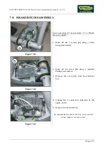
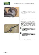
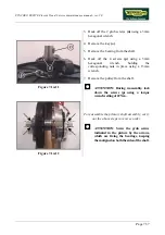
Figure 7.14-1
Carry out the operations described in paragraph
7.13. “Disassembling the belts” as far as step 12.
Place the primary shaft assembly on a work
bench:
1.
Back off the screw
(a)
, using a 5mm
hexagonal wrench, and remove the washer
(b)
.
2.
Remove the crank
c
using an extractor tool.
ATTENTION: During reassembly, lock
down the screw (a) using a 35-Nm torque
wrench, applying a drop of Loctite thread
compound.
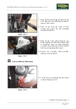
Figure 7.14-2
3.
Back off the 2 grub screws
(d)
using a 3mm
hexagonal wrench.
4.
Remove the key
(e)
.
5.
Remove the bearing from the shaft.
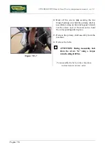
Figure 7.14-3
6.
Remove the spacer
(f)
and the flywheel
assembly
(g)
from the shaft.
Continued on following page
→
Содержание Synchro Excite 500
Страница 1: ...SERVICE MAINTENANCE MANUAL REV 2 0 ...
Страница 2: ......
Страница 4: ......
Страница 10: ...SYNCHRO EXCITE Class Trend Service maintenance manual rev 2 0 Pagina vi Page intentionally left blank ...
Страница 48: ...SYNCHRO EXCITE Class Trend Service maintenance manual rev 2 0 Pagina 4 6 LIBYA DVB T ...
Страница 49: ...SYNCHRO EXCITE Class Trend Service maintenance manual rev 2 0 Page 4 7 Page intentionally left blank ...
Страница 50: ......
Страница 190: ...SYNCHRO EXCITE Class Trend Service maintenance manual rev 2 0 Pagina 9 50 Page intentionally left blank ...
Страница 201: ......

