SYNCHRO EXCITE Class & Trend: Service & maintenance manual - rev. 2.0
Page 7.7
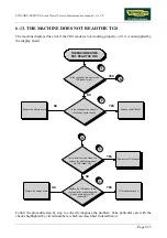
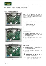
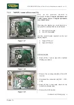
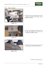
Figure 7.2-10
CPU Board (B):
1.
Disconnect the cables indicated in the figure,
coming from TTL Board [CN3], Touch
screen [CN28A], inverter LCD [CN5] and
headphone jack [J3].
ATTENTION: to disconnect the cable
coming from the touch screen, bend
lightly back the protection plate, if
necessary.
2.
Back off the 6 screws
(e)
with a small
Phillips screwdriver.
3.
Remove the CPU Board.
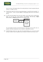
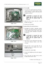
Figure 7.2-11
To disassemble LCD and Touch Screen:
1.
Disconnect the cable’s connectors coming
from TTL and Touch screen [CN3-CN28A],
on CPU Board. On the inverter those
direct
to the LCD inverter indicated in the figure
[CN2-CN3].
ATTENTION: to disconnect the cable
coming from the touch screen, bend
lightly back the protection plate, if
necessary.
2.
Back off the 5 screws
(f)
, which fix the plate
with all the Display Boards, to the front
covering.
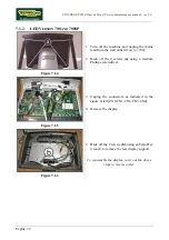
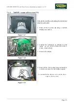
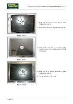
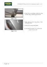
Figure 7.2-12
3.
Back off the 2 screws
(g)
which fix the
headphone jack at the display with a small
Phillips screwdriver.
4.
Disconnect the connector
(h)
.
5.
Remove the headphone jack from the display
housing.
6.
Lift up the plate on which all the circuit
boards and the LCD are fixed.
Continued on following page
→
Содержание Synchro Excite 500
Страница 1: ...SERVICE MAINTENANCE MANUAL REV 2 0 ...
Страница 2: ......
Страница 4: ......
Страница 10: ...SYNCHRO EXCITE Class Trend Service maintenance manual rev 2 0 Pagina vi Page intentionally left blank ...
Страница 48: ...SYNCHRO EXCITE Class Trend Service maintenance manual rev 2 0 Pagina 4 6 LIBYA DVB T ...
Страница 49: ...SYNCHRO EXCITE Class Trend Service maintenance manual rev 2 0 Page 4 7 Page intentionally left blank ...
Страница 50: ......
Страница 190: ...SYNCHRO EXCITE Class Trend Service maintenance manual rev 2 0 Pagina 9 50 Page intentionally left blank ...
Страница 201: ......

