SYNCHRO EXCITE Class & Trend: Service & maintenance manual - rev. 2.0
Pagina 6.32
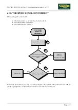
(1)
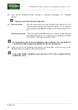
Carry out the “Standard Setting” procedure as detailed at paragraph 9.5.5. “Standard
settings”.
The speed sensor detects the heads of these bolts.
(2)
Powered models
:
Place the tester probes across the terminals of the speed sensor. The
measured signal should be that indicated in Figure 3.2-1. In addition,
when pedaling at 80 RPM the frequency of the signal should be 136
Hz.
Self-Powered models
: Check the signal on
ELT-01
cable. The measured signal should be
that indicated in Figure 3.2-1. In addition, when pedaling at 80 RPM
the frequency of the signal should be 136 Hz.
The speed signal can also be observed qualitatively, using a multimeter. The value should be 0
Vdc when the machine is stopped, and gradually increase as the speed increases.
(3)
Update the low kit SW uploading both firmware and brake table. At the end carry out the
“Default setting” procedure for the low kit parameters.
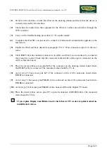
If you replace Display board/Brake board, check that its SW version is updated, otherwise
install the last version.
Содержание Synchro Excite 500
Страница 1: ...SERVICE MAINTENANCE MANUAL REV 2 0 ...
Страница 2: ......
Страница 4: ......
Страница 10: ...SYNCHRO EXCITE Class Trend Service maintenance manual rev 2 0 Pagina vi Page intentionally left blank ...
Страница 48: ...SYNCHRO EXCITE Class Trend Service maintenance manual rev 2 0 Pagina 4 6 LIBYA DVB T ...
Страница 49: ...SYNCHRO EXCITE Class Trend Service maintenance manual rev 2 0 Page 4 7 Page intentionally left blank ...
Страница 50: ......
Страница 190: ...SYNCHRO EXCITE Class Trend Service maintenance manual rev 2 0 Pagina 9 50 Page intentionally left blank ...
Страница 201: ......

