background image


      83-517-000 Rev.


 A 


    33 

-
-

Rem.sense

Local  sense

Local sense

Rem.sense

+
+

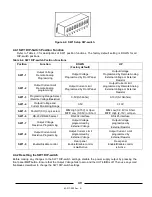
Load lines,  twisted pair, 
shortest length possible.

+V

-V

Load#1

+

Load#3

+

Load#2

+

Power 
Supply

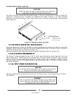
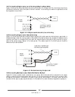
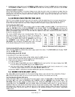
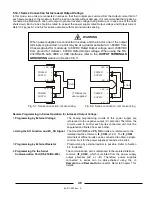
Fig.3-13: Multiple loads connection, radial distribution, local sense

Figure 3-12: Multiple Loads Connection, Radial Distribution, Local Sense 

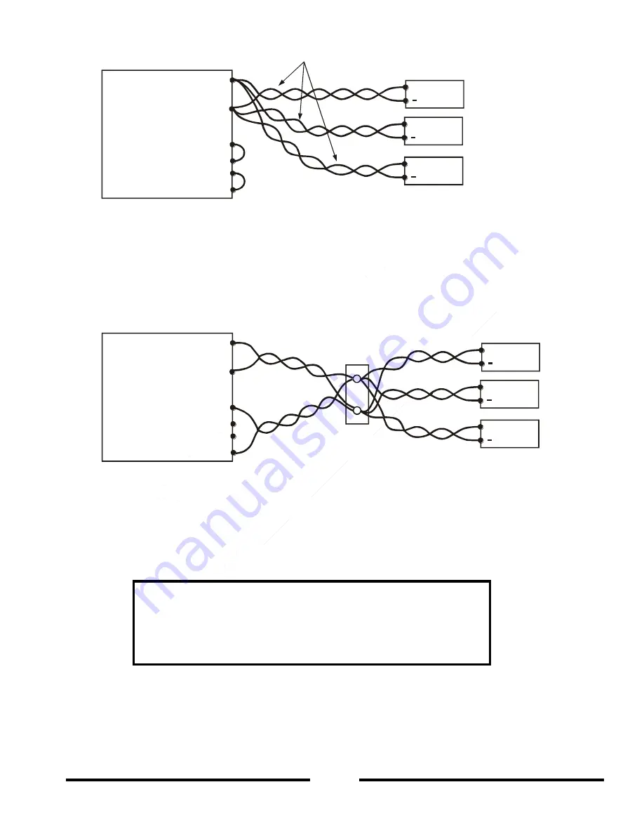
 Multiple Load Connection with Distribution Terminals 

3.9.10

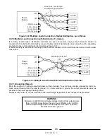
If  remotely  located  output  distribution  terminals  are  used,  the  power  supply  output  terminals  should  be 
connected to the distribution terminals by a pair of twisted and/or shielded wires. Each load should be separately 
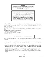
connected to the remote distribution terminals (see Figure 3-13). 
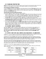
If remote sensing is required, the sensing wires should be connected to the distribution terminals or at the most 
critical load.  


Figure 3-13: Multiple Load Connection with Distribution Terminal 

 Grounding Outputs 

3.9.11

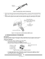
Either the positive or negative output terminals can be grounded. To avoid noise problems caused by common-
mode  current  flowing  from  the  load  to  ground,  it  is  recommended  to  ground  the  output  terminal  as  close  as 
possible to the power supply chassis ground. 
Always use two wires to connect the load to the power supply regardless of how the system is grounded. 


-
-

Rem.sense

Local  sense

Local sense

Rem.sense

+
+

Distribution terminal

+V

+V

-V

-V

Load#1

+

Load#3

+

Load#2

+

Power 
Supply

Fig.3-14: Multiple loads connection with distribution terminal

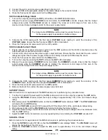
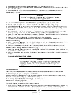
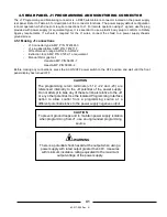
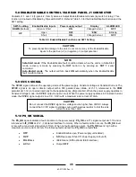
                          WARNING 

Models up to 60VDC Rated Output voltage shall not float outputs more 

than +/-60VDC above/below chassis ground. Models with > 60VDC 

Rated Output voltage shall not float outputs more than +/-600VDC 

above/below chassis ground. 

Содержание GENESYS GEN 2400W Series

Страница 1: ... TECHNICAL MANUAL FOR 1U GENESYS 2 4kW PROGRAMMABLE DC POWER SUPPLIES Document 83 517 000 Rev A TDK Lambda Americas Inc 405 ESSEX ROAD NEPTUNE NJ 07753 TEL 1 732 922 9300 FAX 1 732 922 9334 WEB www us tdk lambda com hp ...

Страница 2: ...83 517 000 Rev A THIS PAGE INTENTIONALLY LEFT BLANK ...

Страница 3: ......

Страница 4: ......

Страница 5: ...al Supplement FOR UNITS EQUIPPED WITH LAN OPTION REFER TO USER S MANUAL P N 83 034 100 FOR UNITS EQUIPPED WITH IEMD OPTION REFER TO USER S MANUAL P N 83 030 200 FOR UNITS EQUIPPED WITH USB OPTION REFER TO USER S MANUAL P N 83 033 800 ...

Страница 6: ...83 517 000 Rev A THIS PAGE INTENTIONALLY LEFT BLANK ...

Страница 7: ... 3 3 CHAPTER 2 SPECIFICATIONS 18 2 1 OUTPUT RATING 18 2 2 AUXILIARY OUTPUTS 18 2 3 INPUT CHARACTERISTICS 18 2 4 CONSTANT VOLTAGE MODE 18 2 5 CONSTANT CURRENT MODE 18 2 6 ANALOG PROGRAMMING AND MONITORING 18 2 7 PROGRAMMING AND READBACK RS 232 485 OPTIONAL LAN IEEE USB INTERFACE 18 2 8 PROTECTIVE FUNCTIONS 19 2 9 FRONT PANEL 19 2 10 ENVIRONMENTAL CONDITIONS 19 2 11 MECHANICAL CONSTRUCTION 19 2 12 E...

Страница 8: ...10 3 J2 Sense Connector Technical Information 35 3 10 4 3 11 REPACKAGING FOR SHIPMENT 35 CHAPTER 4 FRONT AND REAR PANEL CONTROLS AND CONNECTORS 36 4 1 INTRODUCTION 36 4 2 FRONT PANEL CONTROLS AND INDICATORS 36 4 3 REAR PANEL 38 Auxiliary Power Supply 39 4 3 1 4 4 REAR PANEL SW1 SETUP SWITCH 39 SW1 DIP Switch Position Function 40 4 4 1 Resetting the SW1 DIP switch 40 4 4 2 4 5 REAR PANEL J1 PROGRAM...

Страница 9: ...6 6 6 REMOTE MONITORING OF OUTPUT VOLTAGE AND CURRENT 57 CHAPTER 7 RS 232 RS 485 REMOTE CONTROL 58 7 1 INTRODUCTION 58 7 2 CONFIGURATION 58 Default setting 58 7 2 1 Address Setting 58 7 2 2 RS 232 or RS 485 Selection 58 7 2 3 Baud Rate Setting 58 7 2 4 Setting the Unit into Remote or Local Mode 58 7 2 5 RS 232 RS 485 Port in Local Mode 59 7 2 6 Front Panel in Remote Mode 59 7 2 7 7 3 REAR PANEL RS...

Страница 10: ...420 72 8 2 2 8 3 ISOLATED PROGRAMMING MONITORING CONNECTOR 73 8 4 SETUP AND OPERATING INSTRUCTIONS 74 Setting up the Power Supply for 0 5V 0 10V Isolated Programming and Monitoring 74 8 4 1 Setting up the Power Supply for 4 20mA Isolated Programming and Monitoring 74 8 4 2 8 5 PARALLEL OPERATION WITH ISOLATED ANALOG OPTION 75 Setting Up The Master Unit 75 8 5 1 Setting Up The Slave Unit 75 8 5 2 C...

Страница 11: ...a Americas Inc for warranty service the buyer shall prepay shipping charges to TDK Lambda Americas Inc If the unit is covered under the foregoing warranty then TDK Lambda Americas Inc shall pay the shipping charges to return the product to the buyer Refer to Section 3 11 for repackaging for shipment DISCLAIMER The information contained in this document is subject to change without notice TDK Lambd...

Страница 12: ...zard that might cause personal injury WARNING OUTPUT TERMINAL GROUNDING There is a potential shock hazard at the RS 232 RS 485 LAN IEEE and USB ports when using power supplies with rated or combined voltage greater than 400V and the Positive Output of the Power Supply is grounded DO NOT connect the Positive Output to ground when using the RS 232 RS 485 LAN IEEE or USB port under this operating con...

Страница 13: ...ODIFICATIONS Parts substitutions and modifications are allowed by authorized TDK Lambda Americas Inc service personnel only For repairs or modifications the instrument must be returned to an authorized TDK Lambda Americas Inc Service facility ...

Страница 14: ...owing procedure correctly could result in personal injury A WARNING sign should not be skipped and all indicated conditions must be fully understood and met The CAUTION sign denotes a hazard An attention to a procedure is called Not following procedure correctly could result in damage to the equipment Do not proceed beyond a CAUTION sign until all indicated conditions are fully understood and met ...

Страница 15: ...a un risque de choc électrique pouvant provoquer des blessures ATTENTION DANGER MISE A LA TERRE DES BORNES DE SORTIE Il y a un danger de choc électrique sur les ports RS 232 RS 485 LAN IS420 IS520 et IEMD lorsqu on utilise des alimentations électriques ayant à elles seules ou au total une tension supérieure à 400V et si la sortie positive ou negative de l alimentation est raccordée à la terre Ne p...

Страница 16: ...Il attire l attention sur une procédure Si la procédure n est pas suivie correctement il peut en résulter des blessures Le symbole WARNING Attention danger ne doit pas être ignoré et toutes les conditions indiquées doivent être bien comprises et respectées Le symbole CAUTION Attention signale un danger Il attire l attention sur une procédure Si la procédure n est pas suivie correctement l équipeme...

Страница 17: ...er die Trennung der PE Verbindung kann einen möglichen elektrischen Schlag hervorrufen der Personenschäden zur Folge haben kann WARNUNG ERDUNG DER AUSGANGSANSCHLÜSSE Es besteht die Gefahr von möglichen Schlägen an der RS 232 RS 485 LAN IS420 IS520 und den IEMD Anschlüssen wenn Netzgeräte mit höheren Nenn oder kombinierten Spannungen als 400V verwendet werden und die positive oder negative Ausgangs...

Страница 18: ...t auf eine Gefahr hin Die Aufmerksamkeit wird auf ein Verfahren gelenkt Eine Missachtung der Einhaltung des Verfahrens kann zu Personenschaden führen Eine WARNUNG darf nicht übergangen werden und alle angezeigten Umstände müssen vollkommen verstanden und eingehalten werden Das VORSICHTSYMBOL deutet auf eine Gefahr hin Die Aufmerksamkeit wird auf ein Verfahren gelenkt Eine Missachtung der korrekten...

Страница 19: ...ti Eventuali interruzioni del conduttore protettivo di terra o scollegamenti del terminale protettivo di terra porteranno al rischio di scossa elettrica e di conseguente potenziale infortunio AVVERTENZA MESSA A TERRA DEI TERMINALI DI USCITA Vi è rischio di scossa elettrica in corrispondenza delle porte R S232 RS 485 LAN IS420 IS520 e IEMD se si utilizzano alimentatori con tensione nominale o combi...

Страница 20: ...TO denota un periodo È necessario prestare attenzione alla procedura Il mancato rispetto della procedura può sfociare in un infortunio Non ignorare alcun simbolo di AVVERTIMENTO Tutte le condizioni indicate devono essere pienamente comprese e rispettate Il simbolo di ATTENZIONE denota un pericolo È necessario prestare attenzione alla procedura Il mancato rispetto della procedura può sfociare in da...

Страница 21: ...interrupção do condutor de terra de protecção ou corte do terminal de terra de protecção poderá originar um risco de choque passível de provocar ferimentos AVISO LIGAÇÃO À TERRA DE TERMINAIS DE SAÍDA Há a possibilidade de existir risco de choque nas portas RS 232 RS 485 LAN IS420 IS520 e IEMD quando se utilizam fontes de alimentação com tensão nominal ou combinada superior a 400V e a saída positiv...

Страница 22: ...o alimentação O sinal de AVISO assinala um perigo Solicita se atenção para um procedimento Não seguir correctamente o procedimento pode resultar em ferimentos Não se deve ignorar um sinal de AVISO e todas as condições indicadas devem ser compreendidas e respeitadas O sinal de CUIDADO assinala um perigo Solicita se atenção para um procedimento Não seguir correctamente o procedimento pode resultar e...

Страница 23: ...de protección o desconexión del borne de tierra de protección supondrá un riesgo potencial de descarga eléctrica que puede llegar a causar daños personales WARNINGADVERTENCIA CONEXIÓN A TIERRA DE LOS BORNES DE SALIDA El uso de fuentes de alimentación con una tensión nominal o combinada superior a 400V y la Salida Positiva o Negativa de la Fuente de Alimentación conectada a tierra representa un rie...

Страница 24: ...TENCIA indica un peligro Llama la atención ante un procedimiento Si el procedimiento no se realiza correctamente podrían producirse lesiones personales Los símbolos de ADVERTENCIA no se pueden pasar por alto y deben comprenderse y cumplirse todas las condiciones indicadas El símbolo de PRECAUCIÓN indica un peligro Llama la atención ante un procedimiento Si el procedimiento no se realiza correctame...

Страница 25: ...and Preview the settings The rear panel includes the necessary connectors to control and monitor the power supply operation by remote analog signals or by the built in serial communication RS 232 RS 485 LAN IEEE and USB programming and Isolated Analog programming monitoring are optional Models Covered by this Manual 1 2 2 Model Voltage range V Current range A GEN 8 300 0 8 0 300 GEN 10 240 0 10 0 ...

Страница 26: ...rogrammed by analog voltage or by resistor and can be monitored by analog voltage The power supply output can be remotely set to On or Off and analog signals monitor the proper operation of the power supply and the mode of operation CV CC Parallel operation 1 2 7 Genesys power supplies of the same output voltage and current rating can be paralleled in a master slave configuration with automatic cu...

Страница 27: ...32 Cables to connect GEN to Serial Port on PC GEN to PC DB9 GEN 232 9 P N 15 507 203 GEN to PC DB25 GEN 232 25 P N 15 507 204 RS 485 Cable to connect GEN to Serial Port on PC GEN to PC DB9 GEN 485 9 P N 15 507 202 AC Cables 1 3 3 AC cables are not provided with the power supply Refer to Table 1 2 for recommended AC input cables customer supplied Add a non locking plug approved by the national safe...

Страница 28: ...urrent 2mA 2 Max Load regulation 11 0 02 of rated Output current 5mA 3 Load regulation thermal drift Less than 0 05 of rated Output current over 30 minutes following load change 4 Ripple rms 5Hz 1MHz 12 mA 700 500 400 250 150 90 60 40 30 12 10 5 5 Temperature coefficient ppm C 70PPM C from rated output current following 30 minutes warm up 6 Temperature stability 0 01 of rated Iout over 8 hrs inter...

Страница 29: ... 2 Dimensions WxHxD mm W 422 8 H 43 6 D 441 0 excluding connectors encoders handles etc 3 Weight kg Less than 10kg 22 lbs 4 AC Input connector with protective cover Single Phase 230VAC models Power Combicon PC 6 16 3 GF 10 16 Series wit h strain relief Three Phase 208VAC 400VAC models Power Combicon PC 6 16 4 GF 10 16 Series with strain relief 5 Output connector 8V to 100V models busbars hole Ø 10...

Страница 30: ...tput voltage rating constant input voltage 12 For 8V 16V models the ripple is measured at 2V to rated Output voltage and rated Output current For other models the ripple is measured at 10 100 of rated Output voltage and rated Output current 13 The constant current programming readback and monitoring accuracy does not include the warm up and load regulation thermal drift 14 Measured with JEITA RC 9...

Страница 31: ...83 517 000 Rev A 21 2 15 GENESYSTM 2400W POWER SUPPLY OUTLINE DRAWING ...

Страница 32: ...pply Section 3 3 2 Installation Installing the power supply Ensuring adequate ventilation Section 3 4 Section 3 5 3 AC source AC source requirements Connecting the power supply to the AC source Section 3 6 Section 3 7 4 Test Turn on checkout procedure Section 3 8 5 Load connection Wire size selection Local Remote sensing Single or multiple loads Section 3 9 6 Default setting The power supply setti...

Страница 33: ...rear panel Upon installation allow cooling air to reach the front panel ventilation inlets Allow a minimum of 10cm 4 inches of unrestricted air space at the front and the rear of the unit The power supply should be used in an area that the ambient temperature does not exceed 50 C 3 6 AC SOURCE REQUIREMENTS The Genesys TM series is designed for use in TN TT and IT power distribution system Dependin...

Страница 34: ...the stripped wires through the strain relief base until the outer cable jacket is flush with the edge of the base Tighten 16 18 lb inch 1 81 2 03Nm the body to the base while holding the cable in place Now the cable is securely fastened inside the strain relief Refer to Figure 3 2 WARNING The AC input cord is not provided with power supply WARNING Some components inside the power supply are at AC ...

Страница 35: ... following procedure ensures that the power supply is operational and may be used as a basic incoming inspection check Refer to Figure 4 1 and Figure 4 2 for the location of the controls indicated in the procedure Prior to Operation 3 8 2 1 Ensure that the power supply is configured to the default setting Front panel AC On Off switch at the OFF position SW1 DIP switch All positions at the DOWN Off...

Страница 36: ... supply model 6 Compare the DVM reading with the front panel CURRENT meter reading to verify the accuracy of the CURRENT meter Ensure that the front panel CURRENT LED is illuminated 7 Press the front panel AC power switch to the OFF position 8 Remove the shunt from across the power supply output terminals OVP Check 3 8 5 Refer to Section 5 3 for explanation of the OVP function prior to performing ...

Страница 37: ...ill display the communication port address 2 Using the VOLTAGE adjust encoder check that the unit address can be set within the range of 0 to 30 Baud Rate Setting RS 232 and RS 485 only 3 8 9 1 Press and hold the REM LOC button for approximately 3 seconds The CURRENT display will show the communication port Baud rate 2 Using the CURRENT adjust encoder check that the Baud rate can be set to 1200 24...

Страница 38: ...ross Lead in feet Cross Sect area mm Resistivity Ohms km Maximum length in meters to limit voltage drop to 1V or less 10A 20A 50A 100A 200A 400A 2 5 8 21 12 0 6 0 2 4 1 2 0 6 0 3 4 5 09 18 6 9 8 4 0 2 1 0 0 5 6 3 39 29 4 14 8 5 8 2 9 1 45 0 7 10 1 95 51 2 25 6 10 2 5 1 2 5 1 25 16 1 24 80 0 40 0 16 0 8 4 2 25 0 795 125 0 62 0 25 2 12 6 6 3 3 1 35 0 565 177 0 88 0 35 4 17 7 8 8 4 4 Table 3 3 Maximu...

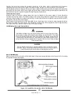
Страница 39: ...d transients such as back EMF from a motor may occur connect a surge suppressor across the output to protect the power supply The breakdown voltage rating of the suppressor must be approximately 10 higher than the maximum Output voltage of the power supply Making the Load Connections 3 9 6 8V to 100V Models Refer to Figure 3 5 for connection of the load wires to the power supply busbars and to Fig...

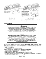
Страница 40: ...Figure 3 8 WARNING Hazardous voltages may exist at the outputs and the load connections when using a power supply with a rated Output voltage greater than 40V To protect personnel against accidental contact with hazardous voltages ensure that the load and its connections have no accessible live parts Ensure that the load wiring insulation rating is greater than or equal to the maximum Output volta...

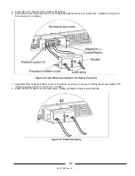
Страница 41: ...ghtening torque 4 8 5 3 Lb inch 0 5 0 6Nm Figure 3 8 Load Wires Connection to the Output Connector 7 Assemble the enclosure bottom cover to it s place as shown in Figure 3 9 using the screw marked C Tightening torque 4 8 5 3 Lb inch 0 5 0 6Nm 8 Slide down the shutter to secure load wires in place and tighten the screw marked B Figure 3 9 Shield Assembly ...

Страница 42: ...assis or the load ground The optimal point for the shield ground should be determined by experimentation Figure 3 11 Remote Sensing Single Load Connecting Multiple Loads Radial Distribution Method 3 9 9 Figure 3 12 shows multiple loads connected to one supply Each load should be connected to the power supply s output terminals using separate pairs of wires It is recommended that each pair of wires...

Страница 43: ... to the distribution terminals or at the most critical load Figure 3 13 Multiple Load Connection with Distribution Terminal Grounding Outputs 3 9 11 Either the positive or negative output terminals can be grounded To avoid noise problems caused by common mode current flowing from the load to ground it is recommended to ground the output terminal as close as possible to the power supply chassis gro...

Страница 44: ...ments With local sensing the Output voltage regulation is made at the output terminals This method does not compensate for voltage drop across the load wires therefore it is recommended only for low load current applications or where the load regulation is less critical Figure 3 14 Sense Connector Location Table 3 4 J2 Terminals Terminal Function J2 1 Remote positive sense S J2 2 Local positive se...

Страница 45: ...to the OFF position connect the open load wire and then turn On the power supply 2 If the power supply is operated without the remote sense lines or local sense jumpers it will continue to work but the output voltage regulation will be degraded Also the OVP circuit may activate and shut down the power supply J2 Sense Connector Technical Information 3 10 4 J2 connector type MC 1 5 5 G 3 81 Phoenix ...

Страница 46: ...TAGE control High resolution rotary encoder for adjusting the Output voltage Also adjusts the OVP UVL levels and selects the unit Address for digital communication 5 2 1 5 3 1 5 4 1 7 2 2 2 VOLTAGE indicator Green LED lights for Constant Voltage mode operation 3 VOLTAGE display 4 digit 7 segment LED display Normally displays the Output voltage When the PREV button is pressed the VOLTAGE display in...

Страница 47: ... to cancel the FOLDback protection 5 5 12 FOLD indicator Green LED lights when FOLDback protection is ON 13 OVP UVL button Over Voltage Protection and Under Voltage Limit setting Press once to set OVP using VOLTAGE encoder the current display shows OUP Press again to set the UVL using VOLTAGE encoder the current display shows UUL 5 3 5 4 14 PREV button Main function Press PREV to display the Outpu...

Страница 48: ... 45 type connector used for daisy chaining power supplies to form a serial communication bus 7 3 7 4 5 Programming and Monitoring connector Connector for Remote Analog interface Includes Output voltage and Output current limit programming and monitoring signals Shut off SO control electrical signal Enable Disable control dry contact Power Supply OK PS_OK signal and operation mode CV CC signal 4 5 ...

Страница 49: ...tor Function Description 4 4 REAR PANEL SW1 SETUP SWITCH The SW1 Setup switch see Figure 4 3 is a 9 position DIP switch that allows the user to choose the following Internal or Remote programming for Output voltage and Output current limit Remote voltage or resistive programming of Output voltage and Output current Limit Select range of Remote voltage and resistive programming Select range of Outp...

Страница 50: ...ut Voltage and Current Monitoring Range 0 5V 0 10V SW1 5 Shut Off SO Logic select ON High 2 15V or Open OFF Low 0 0 6V or Short ON Low 0 0 6V or Short OFF High 2 15V or Open SW1 6 RS 232 RS 485 select RS 232 interface RS 485 interface SW1 7 Output Voltage Resistive Programming Output Voltage programmed by External Voltage Output Voltage programmed by External Resistor SW1 8 Output Current Limit Re...

Страница 51: ...xtraction tool AMP P N 91232 1 or equivalent Manual Pistol grip tool Handle AMP P N 58074 1 Head AMP P N 58063 2 Before making any connections press the AC ON OFF power switch to the OFF position and wait until the front panel display has turned OFF CAUTION The programming return terminals J1 12 22 and 23 are referenced internally to the V potential of the power supply Do not attempt to bias any o...

Страница 52: ...onitoring the power supply Output voltage 6 6 J1 12 COM Control Common Return for VMON IMON CV CC and LOC REM Referenced internally to the negative sense S potential J1 13 CV CC Output for Constant Voltage Constant Current mode indication 5 9 J1 14 ENA_OUT Enable Disable the power supply output by dry contact short open with ENA_IN 5 8 J1 15 SO Input for Shut Off SO control of the power supply out...

Страница 53: ...been completed Then the VOLTAGE meter will display OFF 4 Adjustment resolution can be set to COARSE or FINE resolution Press the FINE button to select between the lower and higher resolution The FINE LED illuminates when the adjustment resolution is set to FINE Constant Current Mode 5 2 2 1 In Constant Current mode the power supply regulates the Output current at the selected value while the load ...

Страница 54: ...Maximum OVP setting levels Activated OVP protection indications 5 3 2 When the Output OVP is activated the power supply output shuts down The VOLTAGE meter displays OUP and the ALARM LED blinks Resetting the OVP circuit 5 3 3 To reset the OVP circuit after it activates 1 Reduce the power supply Output voltage setting below the OVP set level 2 Ensure that the load and the sense wiring are connected...

Страница 55: ...tting the FOLDback protection will be activated again 5 6 OUTPUT ON OFF CONTROL The Output ON OFF Enables or Disables the power supply output Use this function to make adjustments to either the power supply or the load without shutting off the AC input power The Output ON OFF can be activated from the front panel using the OUT button or from the rear panel J1 connector SO or Enable Disable pins Th...

Страница 56: ...current of 10mA 5 10 PS_OK SIGNAL The PS_OK signal indicates a fault condition in the power supply PS_OK is a TTL signal output at J1 16 and is referenced to IF_COM at J1 2 3 Isolated Interface Common When a fault condition occurs the PS_OK level is low with a maximum sink current of 1mA When no fault condition occurs the PS_OK level is high with a maximum source current of 2mA The following fault...

Страница 57: ...TP circuit can be automatic non latched or manual latched depending on the Safe Start or AutoRestart mode 1 Safe Start mode In Safe Start mode the power supply stays OFF after the over temperature condition has been removed The display continues to show O7P and the ALARM LED continues to blink To reset the OTP circuit press the OUT button or send an OUT ON OUT 1 command via the RS 232 RS 485 seria...

Страница 58: ... to control each series connected unit must be separated and floated from each other 2 Using the SO Function and PS_OK Signal The Shut Off SO and PS_OK circuits are referenced to the isolated interface common IF_COM J1 2 3 The IF_COM terminals of different units can be connected to obtain a single control circuit for the power supplies connected in series 3 Programming by External Resistor Program...

Страница 59: ...ve and Negative Output Voltage 1 Programming by External Voltage The analog programming circuits of this power supply are referenced to the negative output V potential Therefore the circuits used to control each series connected unit must be separated and floated from each other 2 Using the SO Function and PS_OK Signal The Shut Off SO and PS_OK circuits are referenced to the isolated interface com...

Страница 60: ...units 2 Set the rear panel setup DIP switch SW1 2 to the UP position 3 Set the rear panel setup DIP switch SW1 3 to the same position as SW1 4 of the Master unit 4 Connect a wire jumper between J1 8 and J1 12 refer to Table 4 4 5 Connect J1 10 IPGM of the Slave unit to J1 25 P of the Master unit 6 Connect J1 23 IPGM_RTN of the Slave unit to J1 12 COM of the Master unit During operation the Slave u...

Страница 61: ...tomatically set the following Output voltage PREView set to approximately 102 of rated Output voltage Output current PREView set to zero amperes UVL set to zero volts OVP to its maximum value AST ON OUT ON FOLDback protection OFF The Master and Slave modes are stored in the individual power supply EEPROM memory when the AC Input power is turned OFF The system will return to the Master Slave operat...

Страница 62: ...tart mode or Auto Restart Setup DIP switch SW1 5 should be set to the DOWN position to enable the Daisy Chain Shut Off operation Other SW1 positions can be set according to the application requirements If a fault occurs in one of the daisy chained units its PS_OK signal will be set to a low level and the unit front panel display will indicate the fault The other units in the daisy chain will Shut ...

Страница 63: ... Panel 5 17 1 In this mode the front panel controls are Enabled so that the user is able to program and monitor the power supply parameters Locked Front Panel 5 17 2 In this mode the following front panel controls are Disabled VOLTAGE and CURRENT encoders FOLD button OUT button The power supply will not respond to attempts to use these controls and the VOLTAGE meter will display LFP to indicate th...

Страница 64: ...put voltage and Output current limit can be programmed via the front panel VOLTAGE and CURRENT encoders or via the J3 RS 232 RS 485 port In Remote Analog mode the Output voltage and Output current limit can be programmed by analog voltage or by programming resistors via J1 9 and J1 10 refer to Sections 6 4 and 6 5 for additional details Refer to Table 6 1 for Local Remote Analog control J1 8 funct...

Страница 65: ...he voltage source 7 Set the programming sources to the desired levels 8 Press the power supply AC Input ON OFF power switch to the ON position 9 Press the OUT button to turn the power supply ON 10 Adjust the programming sources to change the power supply Output voltage and Output current NOTES SW1 4 5 6 and 9 are not required for Remote Analog V I programming Their settings can be determined accor...

Страница 66: ...the programming resistors to the desired resistance 8 Press the AC Input ON OFF power switch to the ON position 9 Press the OUT button to turn the power supply ON 10 Adjust the resistors to change the power supply Output voltage and Output current NOTES 1 SW1 4 5 6 and 9 are not required for Remote Resistive programming Their settings can be determined according to the application requirements 2 T...

Страница 67: ...J1 12 0 5V Down IMON Iout Monitor J1 24 VMON Vout Monitor J1 11 J1 12 0 10V Up IMON Iout Monitor J1 24 Table 6 5 Monitoring Signals Settings Vout Iout Notes 1 Radiated Emissions FCC requirements FCC requirements for radiated emissions Use a shielded cable for the analog control signals If using an unshielded cable attach an EMI ferrite suppressor to the cable as close as possible to the power supp...

Страница 68: ...encoder select the unit Address To preview the power supply Address at any time press and hold the REM LOC button for approximately 3 seconds The VOLTAGE meter will display the power supply Address RS 232 or RS 485 Selection 7 2 3 To select between RS 232 and RS 485 serial communication set the rear panel setup DIP switch SW1 6 position to DOWN RS 232 UP RS 485 Baud Rate Setting 7 2 4 Five optiona...

Страница 69: ...set refer to Section 7 8 the power supply will transmit SRQ s while in Local mode Front Panel in Remote Mode 7 2 7 Front panel control in Remote mode is disabled except for PREView use to preview the Output voltage and Output current settings OVP UVL use to preview the power supply OVP UVL settings LOC REM use to set the unit into Local mode In Local Lockout mode only the PREView and OVP UVL pushb...

Страница 70: ... Section 4 4 RS 232 DOWN position RS 485 UP position 2 Connect the rear panel J3 IN connector to the controller RS 232 or RS 485 port using a suitable shielded cable Refer to Figures 7 2 7 3 and 7 4 for available RS 232 and RS 485 cables Figure 7 2 RS 232 Cable with DB25 Connector P N GEN 232 25 Figure 7 3 RS 232 Cable with DB9 Connector P N GEN 232 9 Figure 7 4 RS 485 Cable with DB9 Connector P N...

Страница 71: ...J3 OUT connector to the next unit J3 IN connector It is recommended that when using several power supplies in a serial communication daisy chain system to connect a 120ohm resistive termination at the last unit J3 OUT RS 485 connector 120Ω 0 5W between TXD and TXD 120Ω 0 5W between RXD and RXD Figure 7 5 Multi Power Supply RS 232 RS 485 Daisy Chain Connection Figure 7 6 Serial Link Cable with RJ 4...

Страница 72: ... 2 for command error messages Error Code Description E01 Returned when program voltage PV is programmed above acceptable range Example PV above 105 of supply rating or PV above 95 of OVP setting E02 Returned when programming output voltage below UVL setting E04 Returned when OVP is programmed below acceptable range Example OVP less than 5 of supply voltage rating plus voltage setting E06 Returned ...

Страница 73: ...d If CR is received the power supply will repeat the last command ID Control Commands 7 7 4 Command Description 1 IDN Returns the power supply model identification as an ASCII string LAMBDA GENX Y 2 REV Returns the software version as an ASCII string 3 SN Returns the unit serial number Up to 12 characters 4 DATE Returns date of last test Date format yyyy mm dd Output Control Commands 7 7 5 Command...

Страница 74: ...e 7 5 The number of characters after OVP is up to 12 The minimum setting level is approximately 105 of the Output voltage setting or the value in Table 7 6 whichever is higher The maximum setting level is shown in Table 5 1 Attempting to program the OVP below this level will result in an execution error response E04 and the OVP setting stays unchanged 16 OVP Returns the setting n where n is the ex...

Страница 75: ...mal point 3 GPC n Program the Output current value in Amperes The range of Output current values is shown in Table 7 4 n may be up to 12 characters plus decimal point 4 GOUT Turns the output to ON or OFF OUT 1 or OUT ON Turn Output ON OUT 0 or OUT OFF Turn Output OFF clears CV and CC bits in the Status Condition STAT register OUT ON will respond with E07 if the output cannot be turned ON because o...

Страница 76: ...imal hex 5 FEVE Reads Fault Event Register Returns 2 digit hex Clears bits of Fault Event Register 6 STAT Reads Status Conditional Register Returns 2 digit hexadecimal hex 7 SENA Sets Status Enable Register using 2 digit hexadecimal hex 8 SENA Reads Status Enable Register Returns 2 digit hexadecimal hex 9 SEVE Reads Status Event register Returns 2 digit hex Clears bits of Status Event register Rat...

Страница 77: ...errors and SRQ registers structure The registers can be read or set via the RS 232 RS 485 serial communication commands When using the LAN IEEE or USB Interface option refer to the specific User s Manual Refer to Figure 7 7 for the Status and Error Registers Diagram Figure 7 7 Status and Error Registers Diagram ...

Страница 78: ... button or OUT 1 command 7 MSB Enable ENA Rear panel J1 Enable terminals J1 1 J1 14 opened Rear panel J1 Enable terminals closed Table 7 7 Fault Condition Register BIT Status name Status symbol Bit Set condition Bit Reset condition 0 LSB Constant Voltage CV Output is ON and the power supply is in CV mode Output is ON and the power supply is NOT in CV mode 1 Constant Current CC Output is ON and the...

Страница 79: ... are received BIT Enable bit name Fault symbol Bit Set condition Bit reset condition 0 LSB Spare bit SPARE Fault condition occurs and it is enabled The fault can set a bit but when the fault clears the bit remains set Entire Event Register is cleared when user sends FEVE command to read the register CLS and AC Input power up also clear the Fault Event Register The Fault Event Register is not clear...

Страница 80: ...tus Enable Register 7 8 3 4 Status Event Register The Status Event Register will set a bit if a change in the power supply status occurs and it is enabled The register is cleared when the SEVE or CLS commands are received A change in this register will generate SRQ BIT Status name Status symbol Bit Set condition Bit reset condition 0 LSB Constant Voltage CV Changes in status occur and it is Enable...

Страница 81: ...ers locally select send line ends with line feed On some PC systems pressing the number keypad Enter will distort displayed messages Use the alphabetic Enter instead Power Supply Set Up 7 9 3 1 Connect the power supply to the PC using the RS 232 cable 2 Set via the front panel Baud Rate 9600 Address 06 3 Set via the rear panel RS 232 RS 485 to RS 232 refer to Section 4 4 Communication Test 7 9 4 1...

Страница 82: ... temperature coefficient ppm C 100 Output Current programming temperature coefficient ppm C 100 Input impedance Ohms 1Meg Absolute maximum voltage VDC 0 15 Max voltage between program inputs and supply outputs VDC 600 Monitoring Outputs Output Voltage monitoring accuracy 1 5 Output Current monitoring accuracy 1 5 Output Impedance see Note Ohms 100 Max voltage between monitoring outputs and supply ...

Страница 83: ... Output Voltage programming input 0 5V 0 10V 4 20mA 3 IPROG_ISO Output Current programming input 0 5V 0 10V 4 20mA 4 GND Ground for programming signals Ground Ground 5 GND Ground for programming signals Ground Ground 6 VMON_ISO Output voltage monitoring output 0 5V 0 10V 4 20mA 7 IMON_ISO Output current monitoring output 0 5V 0 10V 4 20mA 8 SHLD Shield connected internally to chassis of the supply...

Страница 84: ... Input power switch to ON and then pressing the front panel display OUT button Setting up the Power Supply for 4 20mA Isolated Programming and Monitoring 8 4 2 Perform the following procedure to configure the power supply 1 Press the power supply AC Input power switch to the OFF position 2 Connect a wire jumper between J1 8 and J1 12 refer to Table 4 4 3 Set DIP switch SW1 1 to the UP position for...

Страница 85: ...Press the power supply AC Input power switch to the OFF position 2 Connect a wire jumper between J1 8 and J1 12 refer to Table 4 4 3 Set DIP switch SW1 1 to the DOWN position for Output Voltage programming by front panel and SW1 2 to the UP position for Output Current limit external programming 4 Set SW1 3 to select the Programming Voltage Range DOWN 0 5V UP 0 10V 5 Set SW1 4 to select the Monitor...

Страница 86: ...tact a TDK Lambda Americas Inc Sales or Service Facility nearest you Please refer to the TDK Lambda Americas Inc Sales offices addresses listing on the TDK Lambda Americas Inc Programmable High Voltage website http www us tdk lambda com hp 9 6 TROUBLESHOOTING If the power supply appears to be operating improperly use the Troubleshooting Guide Table 9 1 to determine whether the power supply load or...

Страница 87: ...eck rear panel J1 ENABLE connection 5 8 SW1 DIP switch setting 4 4 Display indicates SO Check rear panel J1 Output Shut Off SO connection 5 7 Display indicates OTP Check if air intake or exhaust are blocked Check if the unit is installed adjacent to heat generating equipment 5 12 Display indicates Fb Check Foldback setting and load current 5 5 Poor Load regulation Front panel CV LED is illuminated...

Страница 88: ...7 line feed 61 71 linking power supplies 17 61 local operation 41 43 53 local sense 18 34 25 32 33 35 lock front panel 19 37 53 M maintenance 2 76 Master Slave 15 18 47 50 51 58 64 Multi Drop 16 61 O OTP 37 46 47 65 68 69 77 outline 19 21 Over Voltage 15 16 19 43 44 50 64 68 69 77 P parallel operation 15 16 18 37 42 47 50 51 52 65 75 parity 61 71 preview 15 19 26 37 43 44 51 53 57 59 63 PS_OK 38 3...

Отзывы: