6-15
6-15
THDC / THDCP - 954 / 955 / 974 (Rev. 06/03)
THDC / THDCP - 954 / 955 / 974 (Rev. 06/03)
swit
switch (S5).
ch (S5). Heater swi
Heater switch (S5) is power
tch (S5) is powered by cir-
ed by cir-
cuit break
cuit breaker (CB8).
er (CB8). There is a diode betwee
There is a diode between cir-
n cir-
cuit break
cuit breaker (CB8) and heater s
er (CB8) and heater switc
witch (S5).
h (S5). Its pur-
Its pur-
pose is to prevent an induced voltage generated
pose is to prevent an induced voltage generated
by the heater fan motor (B5), which could prolong
by the heater fan motor (B5), which could prolong
engine shut down, after the ignition switch (S1) is
engine shut down, after the ignition switch (S1) is
turned to the Off pos
turned to the Off position.
ition. With the heater s
With the heater switc
witch
h
(S5) in the Low / High position, 12 VDC will be
(S5) in the Low / High position, 12 VDC will be
present on wire #43 to the heater fan motor (B5)
present on wire #43 to the heater fan motor (B5)
for low speed oper
for low speed operation.
ation. With the heater s
With the heater switch
witch
(S5) in the High position, 12 VDC will be present
(S5) in the High position, 12 VDC will be present
on wire #44 to the heater fan motor (B5) for high
on wire #44 to the heater fan motor (B5) for high
speed operati
speed operation.
on. The heater fan m
The heater fan motor (B5)
otor (B5) is
is
connected to the chas
connected to the chassis ground by wi
sis ground by wire #11.
re #11. The
The
heater fan motor (B5) will circulate air through a
heater fan motor (B5) will circulate air through a
heater coil (which is heated by the engine coolant)
heater coil (which is heated by the engine coolant)
and into the cab.
and into the cab.
Air Condit
Air Conditioner /
ioner / Heater Unit
Heater Unit
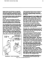
(B7, Illustration
(B7, Illustration
6-16)
6-16)
..
The air conditioner / heater unit (B7) is
The air conditioner / heater unit (B7) is
powered by circ
powered by circuit breaker (C
uit breaker (CB16).
B16). T
Two power
wo power
wires #72 are sent from the circuit breaker (CB16)
wires #72 are sent from the circuit breaker (CB16)
to the air conditi
to the air conditioner / heater unit (B7)
oner / heater unit (B7).
. This is
This is
required to deliver the sufficient amperage to the
required to deliver the sufficient amperage to the
air conditi
air conditioner / heater
oner / heater.
. All control
All controls to the air con-
s to the air con-
ditioner / heater unit (B7) are internal to the air
ditioner / heater unit (B7) are internal to the air
conditioner / heater unit (refer to
conditioner / heater unit (refer to
Section 20A
Section 20A
for
for
additional information on the air conditioner / heat-
additional information on the air conditioner / heat-
er unit).
er unit).
Forward Alarm
Forward Alarm
(LS4, Illustrations 6-16, 9C-2, and
(LS4, Illustrations 6-16, 9C-2, and
29-30)
29-30)
..
The forward alarm circuit is designed to
The forward alarm circuit is designed to
emit an audible alarm when the shifter is in the
emit an audible alarm when the shifter is in the
forward position and the forward alarm circuit has
forward position and the forward alarm circuit has
been activated.
been activated. The forward alar
The forward alarm circ
m circuit is con-
uit is con-
trolled by two switches, the forward alarm key
trolled by two switches, the forward alarm key
switch (S14) and the forward alarm toggle switch
switch (S14) and the forward alarm toggle switch
(S10).
(S10). The forwar
The forward alarm mode key s
d alarm mode key switch (S
witch (S14)
14)
is an on and off swi
is an on and off switch.
tch. When the forwar
When the forward alarm
d alarm
mode key switch (S14) is in the Automatic Posi-
mode key switch (S14) is in the Automatic Posi-
tion, the contac
tion, the contacts of the swi
ts of the switch are clos
tch are closed.
ed. When
When
the forward alarm mode key switch (S14) is off
the forward alarm mode key switch (S14) is off
(Operator Controlled Mode), the contacts of the
(Operator Controlled Mode), the contacts of the
swit
switch are open.
ch are open. With the forw
With the forward alarm m
ard alarm mode
ode
key switch (S14) turned to the Automatic Position,
key switch (S14) turned to the Automatic Position,
the forward alarm (LS4) will always be energized,
the forward alarm (LS4) will always be energized,
sounding an audible alarm any time the shifter is
sounding an audible alarm any time the shifter is
placed in the forw
placed in the forward position
ard position.
. With the forw
With the forward
ard
alarm override switch (S14) turned to the Operator
alarm override switch (S14) turned to the Operator
Controlled position, the forward alarm toggle
Controlled position, the forward alarm toggle
switch (S10) can activate the forward alarm circuit
switch (S10) can activate the forward alarm circuit
when the shifter
when the shifter is in the forw
is in the forward position.
ard position. This
This
allows the operator to determine when or when
allows the operator to determine when or when
not to use the forward alarm ci
not to use the forward alarm circuit.
rcuit. With the shift
With the shift--
er in the forward position, 12 VDC is sent on wire
er in the forward position, 12 VDC is sent on wire
#306 to pin 14 of forwa
#306 to pin 14 of forward rel
rd relay (K17)
ay (K17).
. Grou
Ground to
nd to
ener
energiz
gize K17 is suppli
e K17 is supplied by either S1
ed by either S10 or S14.
0 or S14. 12
12
VDC is supplied by circuit breaker (CB19) at all
VDC is supplied by circuit breaker (CB19) at all
tim
times to pin 9 (comm
es to pin 9 (common pin) of K17.
on pin) of K17. When K17
When K17
energizes, the 12 VDC at pin 9 will pass out pin 5
energizes, the 12 VDC at pin 9 will pass out pin 5
to LS4 (forward alarm unit), energizing it.
to LS4 (forward alarm unit), energizing it.
WARNING:
WARNING:
See the information in the
See the information in the
Operator’s Guide
Operator’s Guide
and
and
Safety Check
Safety Check
concerning
concerning
selecting the
selecting the appro
appropriate mode
priate mode of operation.
of operation.
Reverse Alarm
Reverse Alarm
(LS3,
(LS3, Illust
Illustration 6-16
ration 6-16).
). The
The
reverse alarm circuit is designed to emit an audi-
reverse alarm circuit is designed to emit an audi-
ble alarm when the shifter is in the reverse posi-
ble alarm when the shifter is in the reverse posi-
tion.
tion. The reverse alar
The reverse alarm circui
m circuit is controll
t is controlled by the
ed by the
shifter
shifter.
. With the shift
With the shifter in the reverse positi
er in the reverse position,
on,
relay (K18) is ener
relay (K18) is energized.
gized. Circui
Circuit breaker (CB15)
t breaker (CB15)
will supply 12 VDC to pin #30 of relay (K18).
will supply 12 VDC to pin #30 of relay (K18).
When relay (K18) energizes, the 12 VDC present
When relay (K18) energizes, the 12 VDC present
at pin #30 will pass out pin #87 through wire #39,
at pin #30 will pass out pin #87 through wire #39,
energizi
energizing the reverse alar
ng the reverse alarm (LS3).
m (LS3). Any time 12
Any time 12
VDC is present on wire #319 at relay (K18), pin
VDC is present on wire #319 at relay (K18), pin
#86, the reverse alarm (LS3) should be energized.
#86, the reverse alarm (LS3) should be energized.
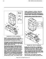
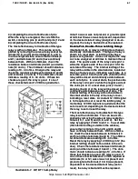
Refer to Illustration 6-16 for component reference
Refer to Illustration 6-16 for component reference
P
Prro
ob
blle
em
m
C
Ca
au
us
se
e
C
Co
orrrre
ec
cttiio
on
n
1.
1. Eng
Eng Oil
Oil lig
light
ht (DS
(DS1)
1)
is illuminated.
is illuminated.
1.
1. Engin
Engine oil p
e oil pres
ressure i
sure is bel
s below 7 - 10
ow 7 - 10
psi.
psi.
2.
2. Defe
Defecti
ctive engi
ve engine oil pr
ne oil press
essure
ure
switch (S17).
switch (S17).
3.
3. Ther
There is a
e is a shor
short on w
t on wire
ire #4.
#4.
1.
1. Refe
Refer to
r to Probl
Problem 36
em 36. in t
. in the
he
Engine Troubleshooting
Engine Troubleshooting
chart in
chart in
Section 1
Section 1
..
2.
2. Repl
Replace en
ace engine o
gine oil p
il pres
ressur
sure
e
switch (S17).
switch (S17).
3.
3. Isol
Isolate an
ate and rep
d repair
air shor
short.
t.
https://www.forkliftpdfmanuals.com/
Содержание THDC-954
Страница 4: ...https www forkliftpdfmanuals com...
Страница 6: ...https www forkliftpdfmanuals com...
Страница 16: ...1 2 1 2 Rev Rev 11 94 11 94 https www forkliftpdfmanuals com...
Страница 18: ...https www forkliftpdfmanuals com...
Страница 20: ...https www forkliftpdfmanuals com...
Страница 48: ...1 27 1 27 THDC THDCP 954 955 974 Rev 06 03 THDC THDCP 954 955 974 Rev 06 03 https www forkliftpdfmanuals com...
Страница 56: ...2 3 2 3 THDC THDCP 954 955 974 Rev 06 03 THDC THDCP 954 955 974 Rev 06 03 https www forkliftpdfmanuals com...
Страница 60: ...3 3 3 3 THDC THDCP 954 955 974 Rev 06 03 THDC THDCP 954 955 974 Rev 06 03 https www forkliftpdfmanuals com...
Страница 62: ...4 1 4 1 THDC THDCP 954 955 974 Rev 06 03 THDC THDCP 954 955 974 Rev 06 03 https www forkliftpdfmanuals com...
Страница 68: ...5 5 5 5 THDC THDCP 954 955 974 Rev 06 03 THDC THDCP 954 955 974 Rev 06 03 https www forkliftpdfmanuals com...
Страница 88: ...6 19 6 19 THDC THDCP 954 955 974 Rev 06 03 THDC THDCP 954 955 974 Rev 06 03 https www forkliftpdfmanuals com...
Страница 90: ...6 21 6 21 THDC THDCP 954 955 974 Rev 06 03 THDC THDCP 954 955 974 Rev 06 03 https www forkliftpdfmanuals com...
Страница 94: ...6 25 6 25 THDC THDCP 954 955 974 Rev 06 03 THDC THDCP 954 955 974 Rev 06 03 https www forkliftpdfmanuals com...
Страница 95: ...THDC THDCP 954 955 974 Rev 06 03 THDC THDCP 954 955 974 Rev 06 03 6 26 6 26 https www forkliftpdfmanuals com...

