THDC / THDCP - 954 / 955 / 974 (Rev. 06/03)
THDC / THDCP - 954 / 955 / 974 (Rev. 06/03)
6-4
6-4
Component
Component T
Troubleshooting
roubleshooting
Alternator.
Alternator.
The alternator provides 13.8 - 14.4
The alternator provides 13.8 - 14.4
VDC at 100 amps of power for the electrical sys-
VDC at 100 amps of power for the electrical sys-
tem and trickle charges the battery when the
tem and trickle charges the battery when the
engine is being ope
engine is being operated.
rated. When the alter
When the alternator is
nator is
started, it will output 6 VDC to a relay (K3), ener-
started, it will output 6 VDC to a relay (K3), ener-
gizing the relay and taking away the ground from
gizing the relay and taking away the ground from
the Battery light (DS3
the Battery light (DS3
,,
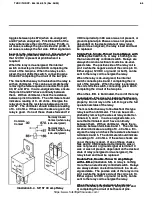
Illustration 6-16) on the
Illustration 6-16) on the
instrum
instrument
ent panel.
panel.
The most effective way to troubleshoot an alterna-
The most effective way to troubleshoot an alterna-
tor is with an ammeter on the output of the alter-
tor is with an ammeter on the output of the alter-
nator
nator.
. Another good check i
Another good check is with a volt
s with a voltmeter
meter
across the batt
across the battery
ery.
. With the engine oper
With the engine operating at a
ating at a
moderate speed, the voltmeter reading should
moderate speed, the voltmeter reading should
never exceed 1
never exceed 15.5 VDC.
5.5 VDC. If reading ex
If reading exceeds 15.5
ceeds 15.5
VDC, the alternator is defective and requires
VDC, the alternator is defective and requires
replacing.
replacing. Should the al
Should the alternator
ternator output drop
output drop
below 12 VDC, the alternator is defective and
below 12 VDC, the alternator is defective and
requires
requires replaci
replacing.
ng.
Perform the following procedures below for abnor-
Perform the following procedures below for abnor-
mal charging system operation.
mal charging system operation.
1.
1. Insure
Insure that the
that the undercharged
undercharged condition
condition (below
(below
12 VDC) has not been caused by accessories
12 VDC) has not been caused by accessories
having been left on for extended periods of
having been left on for extended periods of
time.
time.
2.
2. Chec
Check the driv
k the drive belt for prop
e belt for proper tens
er tension (re
ion (refer to
fer to
Alternator Drive Belt Tension
Alternator Drive Belt Tension
in
in
Section 1
Section 1
).
).
3.
3. Ensur
Ensure that bat
e that battery i
tery is good and c
s good and capabl
apable of
e of
holding a charge.
holding a charge.
4.
4. Insp
Inspect t
ect the wi
he wiring
ring for de
for defect
fects.
s. Chec
Check all
k all con-
con-
nections for tightness and cleanliness, includ-
nections for tightness and cleanliness, includ-
ing the slip connectors at the alternator and
ing the slip connectors at the alternator and
connections at
connections at the
the battery
battery..
5.
5. Wit
With the igni
h the ignition sw
tion switc
itch on and all wir
h on and all wiring har
ing har--
ness leads connected, connect a voltmeter
ness leads connected, connect a voltmeter
from:
from:
a.
a. alternator
alternator “BA
“BAT” te
T” terminal
rminal to ground
to ground
b.
b. alte
alternat
rnator #1 te
or #1 term
rminal t
inal to grou
o ground
nd
c.
c. alte
alternat
rnator #2 te
or #2 term
rminal
inal to gro
to ground
und
An
An infinity
infinity reading
reading indicates
indicates an
an open
open circuit
circuit
between the voltmeter connection and bat-
between the voltmeter connection and bat-
tery
tery.
. Repair i
Repair if require
f required.
d.
6.
6. With al
With all acces
l accessories
sories turned of
turned off, connec
f, connect a volt
t a volt--
meter acr
meter across the battery
oss the battery.
. Operate engine at
Operate engine at
mode
moderate spe
rate speed.
ed. If volt
If voltage is 15.5 VDC or
age is 15.5 VDC or
higher, replace the alternator.
higher, replace the alternator.
Circuit Breakers.
Circuit Breakers.
Circuit breakers are employed
Circuit breakers are employed
in the electrical system and act similar to fuses,
in the electrical system and act similar to fuses,
protecting the electrical circuits and valuable com-
protecting the electrical circuits and valuable com-
ponents from overloads which could damage
ponents from overloads which could damage
them.
them. Perform t
Perform the followi
he following troubleshooti
ng troubleshooting pro-
ng pro-
cedures to troubleshoot a circuit breaker.
cedures to troubleshoot a circuit breaker.
1.
1. Tur
Turn the ignit
n the ignition key
ion key to the “
to the “Ignition”
Ignition” position.
position.
2.
2. If the cir
If the circuit break
cuit breaker is tr
er is tripped, reset
ipped, reset the circ
the circuit
uit
breaker.
breaker.
3.
3. If the c
If the circuit
ircuit breaker
breaker immedi
immediately r
ately retrips,
etrips,
remove all wires from the output side (load
remove all wires from the output side (load
side) of the circuit breaker.
side) of the circuit breaker.
4.
4. Res
Reset the ci
et the circu
rcuit brea
it breaker
ker.
. If the ci
If the circu
rcuit bre
it breaker
aker
retrips, the circuit breaker is bad and must be
retrips, the circuit breaker is bad and must be
replaced.
replaced.
5.
5. If the cir
If the circui
cuit break
t breaker main
er maintai
tains a set state, on
ns a set state, one
e
of the output circ
of the output circuits is s
uits is shorted.
horted. Reconnect
Reconnect
the wires one by one to the output side (load
the wires one by one to the output side (load
side) until the cir
side) until the circuit breaker tr
cuit breaker trips.
ips. Tr
Trouble-
ouble-
shoot the circuit of the wire, that tripped the
shoot the circuit of the wire, that tripped the
circu
circuit breaker, for
it breaker, for a
a short.
short.
6.
6. Isol
Isolate and remo
ate and remove the shor
ve the short from th
t from the circ
e circuit.
uit.
Automatic 90 amp Circuit Breaker
Automatic 90 amp Circuit Breaker
(Illustration
(Illustration
1-5)
1-5)
..
The automatic circuit breaker (CB1) is
The automatic circuit breaker (CB1) is
located on the right s
located on the right side of engine.
ide of engine. It will aut
It will automat-
omat-
ically r
ically reset itself if i
eset itself if it trips.
t trips. If the circui
If the circuit breaker
t breaker
cannot maintain a set state, perform the following
cannot maintain a set state, perform the following
troubleshooting procedures to troubleshoot the
troubleshooting procedures to troubleshoot the
automatic circuit breaker.
automatic circuit breaker.
1.
1. T
Turn the ig
urn the igniti
nition key to the Of
on key to the Off posi
f position
tion..
2.
2. Rem
Remove all w
ove all wire
ires from t
s from the output s
he output side (l
ide (load
oad
side) of the circuit breaker.
side) of the circuit breaker.
3.
3. Tur
Turn the ignit
n the ignition key
ion key to the “
to the “Ignition”
Ignition” position.
position.
If the circuit breaker retrips, the circuit breaker
If the circuit breaker retrips, the circuit breaker
is bad and must be replaced.
is bad and must be replaced.
4.
4. If the cir
If the circui
cuit break
t breaker main
er maintai
tains a set state, on
ns a set state, one
e
of the output circ
of the output circuits is s
uits is shorted.
horted. Reconnect
Reconnect
the wires one by one to the output side (load
the wires one by one to the output side (load
side) until the cir
side) until the circuit breaker tr
cuit breaker trips.
ips. Tr
Trouble-
ouble-
shoot the circuit of the wire, that tripped the
shoot the circuit of the wire, that tripped the
circu
circuit breaker, for
it breaker, for a
a short.
short.
5.
5. Isol
Isolate and remo
ate and remove the shor
ve the short from th
t from the circ
e circuit.
uit.
Single-
Single-Pole, Single-Th
Pole, Single-Throw 30
row 30 amp Relays
amp Relays
(Illustration 6-4)
(Illustration 6-4)
..
A relay is nothing more than an
A relay is nothing more than an
electri
electrically contr
cally controlled switc
olled switch.
h. Relays are always
Relays are always
shown on electrical circuits in a de-energized
shown on electrical circuits in a de-energized
state.
state. The internal s
The internal switch, c
witch, common at pin 30,
ommon at pin 30,
https://www.forkliftpdfmanuals.com/
Содержание THDC-954
Страница 4: ...https www forkliftpdfmanuals com...
Страница 6: ...https www forkliftpdfmanuals com...
Страница 16: ...1 2 1 2 Rev Rev 11 94 11 94 https www forkliftpdfmanuals com...
Страница 18: ...https www forkliftpdfmanuals com...
Страница 20: ...https www forkliftpdfmanuals com...
Страница 48: ...1 27 1 27 THDC THDCP 954 955 974 Rev 06 03 THDC THDCP 954 955 974 Rev 06 03 https www forkliftpdfmanuals com...
Страница 56: ...2 3 2 3 THDC THDCP 954 955 974 Rev 06 03 THDC THDCP 954 955 974 Rev 06 03 https www forkliftpdfmanuals com...
Страница 60: ...3 3 3 3 THDC THDCP 954 955 974 Rev 06 03 THDC THDCP 954 955 974 Rev 06 03 https www forkliftpdfmanuals com...
Страница 62: ...4 1 4 1 THDC THDCP 954 955 974 Rev 06 03 THDC THDCP 954 955 974 Rev 06 03 https www forkliftpdfmanuals com...
Страница 68: ...5 5 5 5 THDC THDCP 954 955 974 Rev 06 03 THDC THDCP 954 955 974 Rev 06 03 https www forkliftpdfmanuals com...
Страница 88: ...6 19 6 19 THDC THDCP 954 955 974 Rev 06 03 THDC THDCP 954 955 974 Rev 06 03 https www forkliftpdfmanuals com...
Страница 90: ...6 21 6 21 THDC THDCP 954 955 974 Rev 06 03 THDC THDCP 954 955 974 Rev 06 03 https www forkliftpdfmanuals com...
Страница 94: ...6 25 6 25 THDC THDCP 954 955 974 Rev 06 03 THDC THDCP 954 955 974 Rev 06 03 https www forkliftpdfmanuals com...
Страница 95: ...THDC THDCP 954 955 974 Rev 06 03 THDC THDCP 954 955 974 Rev 06 03 6 26 6 26 https www forkliftpdfmanuals com...

