Section 3
Section 3
Air Intake System
Air Intake System
C /
C
/
/
/
C /
C
/
/
/
INDICATES AIR FLOW
INDICATES AIR FLOW
COTTER PIN
COTTER PIN
INTERNAL
INTERNAL
FILTER
FILTER
INDICATOR
INDICATOR
SAFETY
SAFETY
FILTER
FILTER
WING
WING
NUT
NUT
PRIMARY
PRIMARY
FILTER
FILTER
ASSEMBL
ASSEMBLY
Y
VACUATOR
VACUATOR
PRECLEANER
PRECLEANER
CAP
CAP
AIR
AIR RESTRICTION
RESTRICTION
INDICATOR
INDICATOR
AIR
AIR
CLEANER
CLEANER
HOUSING
HOUSING
SAFETY
SAFETY
FITTING
FITTING
IF EQUIPPED
IF EQUIPPED
SIGNAL
SIGNAL
LINE
LINE
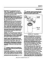
Illust
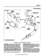
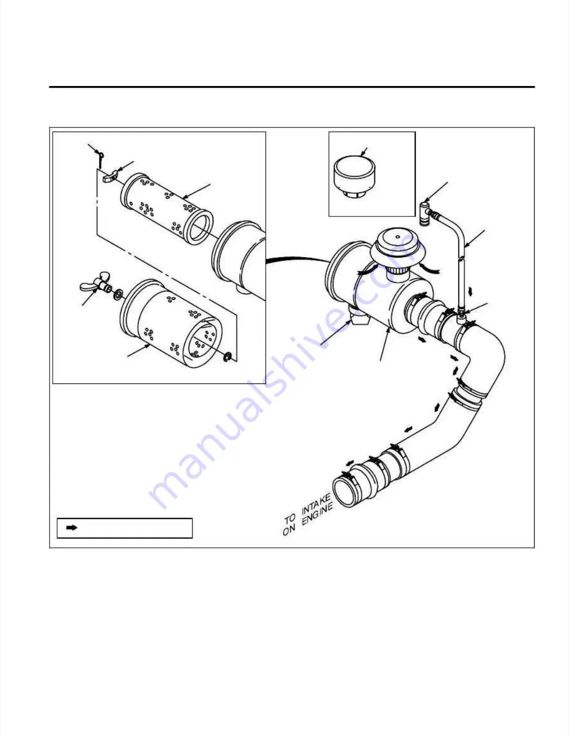
Illustration 3-1.
ration 3-1. Air Intake Syst
Air Intake System Components
em Components
Introduction.
Introduction.
The air cleaner is designed to be
The air cleaner is designed to be
servic
serviced efficient
ed efficiently and quickly
ly and quickly.
. Intake air enters
Intake air enters
the air cleaner through the cap or optional pre-
the air cleaner through the cap or optional pre-
cleaner
cleaner.
. When the air reaches the filt
When the air reaches the filter body
er body, a
, a
helical ramp imparts a high-speed circular motion
helical ramp imparts a high-speed circular motion
to the intake air
to the intake air.
. This act
This action separates up to 85%
ion separates up to 85%
of the dust from the ai
of the dust from the air by centri
r by centrifugal action.
fugal action. The
The
dust is then forc
dust is then forced out the vacuator
ed out the vacuator.
. The air then
The air then
passes through the primary and safety elements,
passes through the primary and safety elements,
where it is cleaned, before entering the engine.
where it is cleaned, before entering the engine.
Major Components
Major Components
(Illustration 3-1)
(Illustration 3-1)
..
The air
The air
cleaner consists of the primary filter element, inter-
cleaner consists of the primary filter element, inter-
nal filter indicator, safety element, air cleaner
nal filter indicator, safety element, air cleaner
housing, cap (or optional precleaner), vacuator
housing, cap (or optional precleaner), vacuator
and
and an
an air restricti
air restriction
on indicator
indicator..
Servicing
Servicing
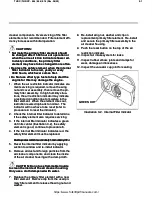
(Illustration 3-1)
(Illustration 3-1)
..
If the equipment is
If the equipment is
being operated under extremely dusty conditions,
being operated under extremely dusty conditions,
the vacuator should be checked every day to be
the vacuator should be checked every day to be
certain it i
certain it is not clogged.
s not clogged. Perform t
Perform the following
he following
procedures to service the filter element and air
procedures to service the filter element and air
https://www.forkliftpdfmanuals.com/
Содержание THDC-954
Страница 4: ...https www forkliftpdfmanuals com...
Страница 6: ...https www forkliftpdfmanuals com...
Страница 16: ...1 2 1 2 Rev Rev 11 94 11 94 https www forkliftpdfmanuals com...
Страница 18: ...https www forkliftpdfmanuals com...
Страница 20: ...https www forkliftpdfmanuals com...
Страница 48: ...1 27 1 27 THDC THDCP 954 955 974 Rev 06 03 THDC THDCP 954 955 974 Rev 06 03 https www forkliftpdfmanuals com...
Страница 56: ...2 3 2 3 THDC THDCP 954 955 974 Rev 06 03 THDC THDCP 954 955 974 Rev 06 03 https www forkliftpdfmanuals com...
Страница 60: ...3 3 3 3 THDC THDCP 954 955 974 Rev 06 03 THDC THDCP 954 955 974 Rev 06 03 https www forkliftpdfmanuals com...
Страница 62: ...4 1 4 1 THDC THDCP 954 955 974 Rev 06 03 THDC THDCP 954 955 974 Rev 06 03 https www forkliftpdfmanuals com...
Страница 68: ...5 5 5 5 THDC THDCP 954 955 974 Rev 06 03 THDC THDCP 954 955 974 Rev 06 03 https www forkliftpdfmanuals com...
Страница 88: ...6 19 6 19 THDC THDCP 954 955 974 Rev 06 03 THDC THDCP 954 955 974 Rev 06 03 https www forkliftpdfmanuals com...
Страница 90: ...6 21 6 21 THDC THDCP 954 955 974 Rev 06 03 THDC THDCP 954 955 974 Rev 06 03 https www forkliftpdfmanuals com...
Страница 94: ...6 25 6 25 THDC THDCP 954 955 974 Rev 06 03 THDC THDCP 954 955 974 Rev 06 03 https www forkliftpdfmanuals com...
Страница 95: ...THDC THDCP 954 955 974 Rev 06 03 THDC THDCP 954 955 974 Rev 06 03 6 26 6 26 https www forkliftpdfmanuals com...


