6-5
6-5
THDC / THDCP - 954 / 955 / 974 (Rev. 06/03)
THDC / THDCP - 954 / 955 / 974 (Rev. 06/03)
toggles between pins 87A (when de-energized)
toggles between pins 87A (when de-energized)
and 87 (when ener
and 87 (when energiz
gized).
ed). Pins 86 and 85 of the
Pins 86 and 85 of the
relay wil
relay will energize the coil of the relay
l energize the coil of the relay.
. Pin 85, in
Pin 85, in
all cases, is always the ground side and pin 86, in
all cases, is always the ground side and pin 86, in
all cases
all cases, is alway
, is always the hot side.
s the hot side. Either sign
Either signal can
al can
be sent to the relay to energi
be sent to the relay to energize it.
ze it. Ensu
Ensure that pin
re that pin
85 is properly grounded, when required, and / or
85 is properly grounded, when required, and / or
that 12 VDC is present at pin 86 when it is
that 12 VDC is present at pin 86 when it is
required.
required.
When the relay is de-energized, the internal
When the relay is de-energized, the internal
switch connects pins 30 and 87A completing the
switch connects pins 30 and 87A completing the
circ
circuit of the two pins.
uit of the two pins. When the relay i
When the relay is ener-
s ener-
gized, the coil shifts the switch, connecting pins
gized, the coil shifts the switch, connecting pins
30 and 87 completing the circuit of the two pins.
30 and 87 completing the circuit of the two pins.
The most effective way to troubleshoot the relay is
The most effective way to troubleshoot the relay is
with an ohmmeter
with an ohmmeter.
. This can be accompl
This can be accomplished by
ished by
removing the female spade connectors from pins
removing the female spade connectors from pins
30, 87, and 87A.
30, 87, and 87A. In a
In a de-en
de-energi
ergized stat
zed state, ensur
e, ensure
e
that pins 30 and 87A have continuity between
that pins 30 and 87A have continuity between
them.
them. With an ohmmeter
With an ohmmeter, check the resis
, check the resistance
tance
betw
between pins 30 and 87a.
een pins 30 and 87a. The ohmm
The ohmmeter sho
eter should
uld
indi
indicate a readi
cate a reading of 0
ng of 0 - 40 ohms.
- 40 ohms. Energ
Energize the
ize the
relay and check the resistance between pins 30
relay and check the resistance between pins 30
and 87.
and 87. The ohmm
The ohmmeter should i
eter should indicate a readi
ndicate a reading
ng
of 0 - 40
of 0 - 40 ohms
ohms.
. If thes
If these two chec
e two checks are good, th
ks are good, the
e
rel
relay is good.
ay is good. If one of these che
If one of these checks fa
cks fails and 12
ils and 12
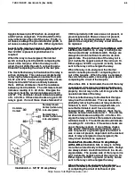
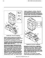
Normally Closed
Normally Closed
Contact (when relay
Contact (when relay
is de-energized)
is de-energized)
Normally Open
Normally Open
Contact (when relay
Contact (when relay
is de-energized)
is de-energized)
Common
Common
Contact
Contact
Illus
Illustration 6-4.
tration 6-4. SP
SP, ST 30 amp Relay
, ST 30 amp Relay
VDC required at pin 86 was or was not present, or
VDC required at pin 86 was or was not present, or
ground signal at pin 85 was or was not present,
ground signal at pin 85 was or was not present,
dependant on the desired state of relay (ener-
dependant on the desired state of relay (ener-
gized or de-energized), the relay is bad and must
gized or de-energized), the relay is bad and must
be replaced.
be replaced.
Single-
Single-Pole, Single-Th
Pole, Single-Throw 10
row 10 amp Relays
amp Relays with
with
L.E.D.s
L.E.D.s
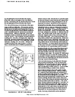
(Illustrati
(Illustration
on 6-5)
6-5)
..
A relay is nothing more
A relay is nothing more
than an electrical
than an electrically control
ly controlled switc
led switch.
h. Relays ar
Relays are
e
always shown on electrical circuits in a de-ener-
always shown on electrical circuits in a de-ener-
gized state.
gized state. The positi
The positive side of the relay c
ve side of the relay coil is
oil is
pin 14 while the negative side of the coil is pin 13.
pin 14 while the negative side of the coil is pin 13.
Either signal, 12 VDC or ground (or both), can be
Either signal, 12 VDC or ground (or both), can be
sent to the relay coil to energize the relay.
sent to the relay coil to energize the relay.
When the relay is de-energized, the internal
When the relay is de-energized, the internal
switch connects pins 9 and 1 completing the cir-
switch connects pins 9 and 1 completing the cir-
cuit of the two pi
cuit of the two pins.
ns. When the relay i
When the relay is energized,
s energized,
the coil shifts the switch, connecting pins 9 and 5
the coil shifts the switch, connecting pins 9 and 5
completing the circuit of the two pins.
completing the circuit of the two pins.
When the L.E.D. is illuminated, the coil of the relay
When the L.E.D. is illuminated, the coil of the relay
is energiz
is energized.
ed. This does not indi
This does not indicate that the con-
cate that the con-
tact points of the internal switches are functioning
tact points of the internal switches are functioning
properly
properly.
. Do not rely on the L.E.D
Do not rely on the L.E.D. to give the full
. to give the full
operational status of the relay.
operational status of the relay.
The most effective way to troubleshoot this type
The most effective way to troubleshoot this type
relay is wi
relay is with an ohmmeter
th an ohmmeter.
. This can be accom-
This can be accom-
plished by removing the wires at relay socket ter-
plished by removing the wires at relay socket ter-
min
minals 9, 5, and 1.
als 9, 5, and 1. In a de-ener
In a de-energize
gized state, en-
d state, en-
sure that terminals 9 and 1 have continuity
sure that terminals 9 and 1 have continuity
between them.
between them. With an ohmm
With an ohmmeter
eter, check the re-
, check the re-
sistanc
sistance between termi
e between terminals 9 and 1.
nals 9 and 1. The ohmme-
The ohmme-
ter sho
ter should indi
uld indicate a readi
cate a reading of 0
ng of 0 - 40 ohms.
- 40 ohms. En-
En-
ergize the relay and check the resistance between
ergize the relay and check the resistance between
termi
terminals 9 and 5.
nals 9 and 5. The ohmmeter s
The ohmmeter should indicate
hould indicate
a readin
a reading of 0
g of 0 - 40 ohms.
- 40 ohms. If thes
If these two chec
e two checks are
ks are
good, the re
good, the relay is goo
lay is good.
d. If one of these chec
If one of these checks
ks
fails and 12 VDC required at terminal 14 was or
fails and 12 VDC required at terminal 14 was or
was not present, or ground signal at terminal 13
was not present, or ground signal at terminal 13
was or was not present, dependant on the desired
was or was not present, dependant on the desired
state of relay (energized or de-energized), the
state of relay (energized or de-energized), the
relay is bad and must be replaced.
relay is bad and must be replaced.
Double-Pole, Double-Throw 10 amp Relays
Double-Pole, Double-Throw 10 amp Relays
with L.E.D.s
with L.E.D.s
(Illustration 6-6)
(Illustration 6-6)
..
A relay is nothing
A relay is nothing
more than an electric
more than an electrically contr
ally controlled swit
olled switch.
ch. Relays
Relays
are always shown on electrical circuits in a de-en-
are always shown on electrical circuits in a de-en-
ergized st
ergized state.
ate. The positi
The positive side of the relay c
ve side of the relay coil is
oil is
pin 14 while the negative side of the coil is pin 13.
pin 14 while the negative side of the coil is pin 13.
Either signal, 12 VDC or ground (or both), can be
Either signal, 12 VDC or ground (or both), can be
sent to the relay coil to energize the relay.
sent to the relay coil to energize the relay.
When the relay is de-energized, the internal
When the relay is de-energized, the internal
switch connects pins (9 and 1) and pins (12 and
switch connects pins (9 and 1) and pins (12 and
4) completing the circuit of both sets of pins.
4) completing the circuit of both sets of pins.
https://www.forkliftpdfmanuals.com/
Содержание THDC-954
Страница 4: ...https www forkliftpdfmanuals com...
Страница 6: ...https www forkliftpdfmanuals com...
Страница 16: ...1 2 1 2 Rev Rev 11 94 11 94 https www forkliftpdfmanuals com...
Страница 18: ...https www forkliftpdfmanuals com...
Страница 20: ...https www forkliftpdfmanuals com...
Страница 48: ...1 27 1 27 THDC THDCP 954 955 974 Rev 06 03 THDC THDCP 954 955 974 Rev 06 03 https www forkliftpdfmanuals com...
Страница 56: ...2 3 2 3 THDC THDCP 954 955 974 Rev 06 03 THDC THDCP 954 955 974 Rev 06 03 https www forkliftpdfmanuals com...
Страница 60: ...3 3 3 3 THDC THDCP 954 955 974 Rev 06 03 THDC THDCP 954 955 974 Rev 06 03 https www forkliftpdfmanuals com...
Страница 62: ...4 1 4 1 THDC THDCP 954 955 974 Rev 06 03 THDC THDCP 954 955 974 Rev 06 03 https www forkliftpdfmanuals com...
Страница 68: ...5 5 5 5 THDC THDCP 954 955 974 Rev 06 03 THDC THDCP 954 955 974 Rev 06 03 https www forkliftpdfmanuals com...
Страница 88: ...6 19 6 19 THDC THDCP 954 955 974 Rev 06 03 THDC THDCP 954 955 974 Rev 06 03 https www forkliftpdfmanuals com...
Страница 90: ...6 21 6 21 THDC THDCP 954 955 974 Rev 06 03 THDC THDCP 954 955 974 Rev 06 03 https www forkliftpdfmanuals com...
Страница 94: ...6 25 6 25 THDC THDCP 954 955 974 Rev 06 03 THDC THDCP 954 955 974 Rev 06 03 https www forkliftpdfmanuals com...
Страница 95: ...THDC THDCP 954 955 974 Rev 06 03 THDC THDCP 954 955 974 Rev 06 03 6 26 6 26 https www forkliftpdfmanuals com...


