6-8
OPERATING PROCEDURES
Model C612
Operating Procedures
6
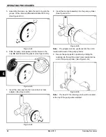
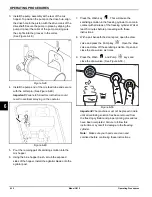
5. Assemble the valve cap. Slide the red O-ring into the
groove of the valve cap.
Do not
lubricate the O-ring.
(See Figure 6-32.)
Figure 6-32
6. Slide the pump valve gasket into the holes on the
cap.
Do not
lubricate the gasket. (See Figure 6-33.)
Figure 6-33
7. Insert the valve cap into the hole in the mix inlet
adapter. (See Figure 6-34.)
Figure 6-34
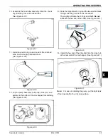
8. Insert the mix inlet assembly into the pump cylinder.
(See Figure 6-35.)
Figure 6-35
Note:
The adapter must be positioned into the notch
located at the end of the pump cylinder.
9. Secure the pump parts in position by sliding the
retaining pin through the cross holes located at one
end of the pump cylinder. (See Figure 6-36.)
Figure 6-36
Note:
The head of the retaining pin should be located
at the top of the pump when installed.
Содержание C612
Страница 8: ...1 4 TO THE INSTALLER Model C612 To the Installer 1 Notes...
Страница 54: ...9 2 PARTS REPLACEMENT SCHEDULE Model C612 Parts Replacement Schedule 9 Notes...
Страница 58: ...10 4 LIMITED WARRANTY ON EQUIPMENT Model C612 Limited Warranty on Equipment 10 Notes...
Страница 62: ...11 4 LIMITED WARRANTY ON PARTS Model C612 Limited Warranty on Parts 11 Notes...

