OPERATING PROCEDURES
6-9
Model C612
Operating Procedures
6
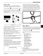
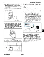
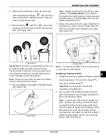
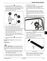
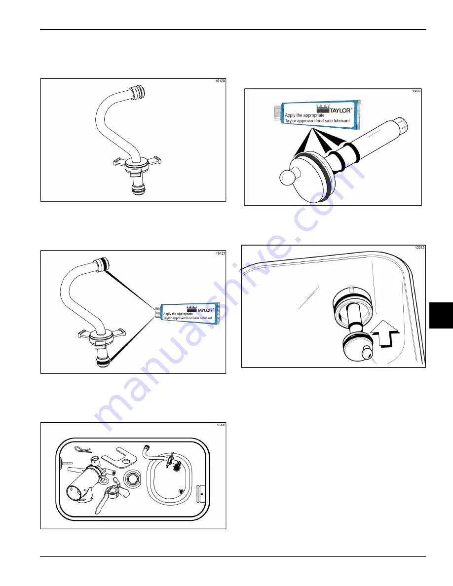
10. Assemble the feed tube assembly. Slide the check
ring into the groove of the feed tube.
(See Figure 6-37.)
Figure 6-37
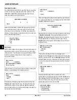
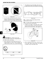
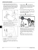
11. Install one red O-ring on each end of the mix feed
tube, and thoroughly lubricate them.
(See Figure 6-38.)
Figure 6-38
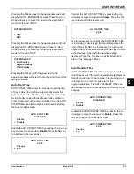
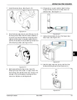
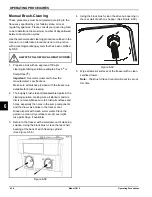
12. Lay the pump assembly, pump clip, cotter pin, and
agitator in the bottom of the mix hopper for sanitizing.
(See Figure 6-39.)
Figure 6-39
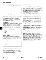
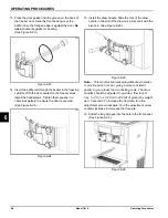
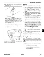
13. Slide the large black O-ring and the two smaller black
O-rings into the grooves on the driveshaft.
Thoroughly lubricate the O-rings and shaft.
Do not
lubricate the hex end of the shaft. (See Figure 6-40.)
Figure 6-40
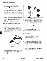
14. Install the hex end of the driveshaft into the drive hub
at the rear wall of the mix hopper. (See Figure 6-41.)
Figure 6-41
Note:
For ease in installing the pump, put the ball crank
of the driveshaft in the 3 o'clock position.
Содержание C612
Страница 8: ...1 4 TO THE INSTALLER Model C612 To the Installer 1 Notes...
Страница 54: ...9 2 PARTS REPLACEMENT SCHEDULE Model C612 Parts Replacement Schedule 9 Notes...
Страница 58: ...10 4 LIMITED WARRANTY ON EQUIPMENT Model C612 Limited Warranty on Equipment 10 Notes...
Страница 62: ...11 4 LIMITED WARRANTY ON PARTS Model C612 Limited Warranty on Parts 11 Notes...

