


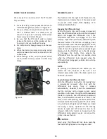


Toe-in adjustment on the front axle is carried out
at the factory and it is set to max 6.5°. This angle is
important for steerability at high speeds, easier
control of the tractor on bends, and simple turning.
You are not recommended to alter this value.
To make this adjustment, after centering the
steering wheel and putting in the tires as a straight
position as possible, lock nut (2) shown in “Figure
“5” is loosened and rods (1) are adjusted by
tightening and loosening them from the key
opening. Normally, front side of the front tires
should be turned in with reference to the rear side,
and the angle between these tires should not
exceed 6.5°. Although the difference between the
track on the front side and the track on the rear
side of the tires differs according to the tire type, a
value of 75-90mm would be convenient.
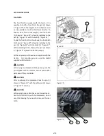
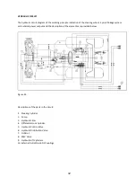
HYDRAULIC LIFT
The hydraulic lift is a system, which is used to lift
and lower the equipment connected to the three-
point lifting system. It carries out these controls
with tubes, hoses, two lifting cylinders, the
hydraulic gear pump and the control valve.
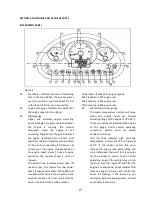
It carries out following functions with levers (20-
21)shown in “Figure 2”:
•
Position Control
•
Depth Control
•
Combination Control
•
Flotation Control
These functions are selected depending on the
work to be done, and soil conditions.
Position Control:
Control is carried out by the lever (21) shown in
“Figure 2”. Pull the lever backwards to lift up the
equipment. Height of the equipment is directly
proportional to the position of the lever. The
application travel is proportional to the position
control lever 18 of the lift.
Depth Control:
Control is carried out by lever (20) shown in “Figure
2”. Immersion depth of the equipment is
proportional to the resistance faced when driving.
The control valve changes the immersion depth of
the equipment in a way to keep constant the
resistance with predetermined value, and allows
constant power consumption. After lifting the
equipment while driving, do not forget to bring it
to the same depth setting when you lower it again.
Combined Control:
You are recommended to use the combination
control when carrying out works having a risk of
passing to subsoiling in regions, whose grading was
not carried out, especially with irregular surface or
soft soil.
Lower the equipment down the ground and adjust
the depth as described above. Lower the position
control lever slowly; in this way you will also make
position control.
In this way, a working possibility is acquired with a
constant power by preventing too deep ploughing.
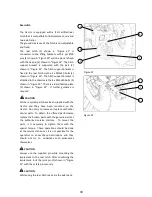
Flotation Control:
Bring both (20) and (21) levers shown in “Figure 2”
to the lowest position.
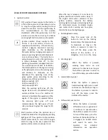
Use the lever (1) shown in “Figure 16” to set its
precision.
If precision is increased during flotation control,
bounce of the equipment increases, and if
precision is decreased, jounce of the equipment
decreases.
Turn it clockwise (A) to increase the precision.
Turn it counterclockwise (B) to decrease the
precision.
Figure 16
1
A
B
Figure 15
1
2
26
Содержание 850
Страница 1: ......
Страница 2: ......
Страница 7: ......
Страница 12: ......
Страница 24: ...12 ...
Страница 28: ...16 ...
Страница 50: ...38 ...
Страница 54: ...42 ...
Страница 78: ...PROPER BATTERY SERVICE AND TIPS FOR SAFETY Table 7 66 ...
Страница 86: ...74 ...
Страница 87: ...SECTION 7 TECHNICAL SPECIFICATIONS Figure 83 Table 8 Technical Specs 75 ...
Страница 89: ...Figure 84 Table 11 Turning Radius 77 ...
Страница 94: ...82 ...
Страница 100: ...88 ...
Страница 101: ......


