


24.
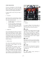
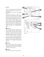
4-Wheel Drive Lever
When lever (2) shown in “Figure 10” is in lower
position, the four wheel drive function activates,
and when it is taken to the upper position, the
function deactivates. When the four wheel drive is
active, roadholding and braking ability improves on
muddy and slippery surfaces and fields. When
activating or deactivating the four wheel drive, be
sure the tractor is at standstill.
Use the four wheel drive function where required
only. Do not use it on hard soil, asphalt, cement
surface and highways; this may cause wheels to
wear.
25.
External Power Outlet Lever
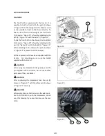
There are external power outlets on the back of
the tractor you can make use of for using in
equipment hydraulics. These are parts of the
hydraulic circuit of the tractor, and they use the
same oil as in the gearbox of the tractor.
The control levers are situated on the left side,
beside the seat. These power outlets can be
connected to the equipment with standard ½”
quick fit coupling connection. Required male
connecting terminals are supplied in the tool box
together with the tractor.
Together with the tractor, there is 1 hydraulic
distribution valve with 2 dual-effect independent
circuits, which can be converted to single-effect..
It can be used to feed single-effect and dual-effect
cylinders.
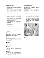
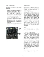
Control arms have 3 positions:
Above: Hydraulic is given from outlet A.
Middle: Circuit is closed.
Below: Hydraulic is given from outlet B.
In order to move the control levers, first pull the
safety lock and the lever (3) shown in “Figure 11”
forward and put the control levers (1-2) shown in
“Figure 11” in the positions you desire. The
pressure oil is driven from “A” or “B” outlets
according to the position taken by the control
lever.
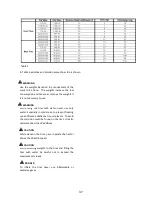
When using an implement, which requires a mass
amount of oil, the oil level on the transmission case
of the tractor may drop below the minimum
baseline. If this happens, components of the
tractor may be damaged due to insufficient
lubricating. To prevent this from happening, be
watchful of oil level when using hydraulic outlets;
and if necessary, replenish oil using the oil
recommended for transmission.
Figure 10
WARNING
1
2
Figure 11
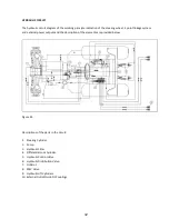
Figure 12
B
A
2
3
1A
1B
2B
2A
4
5
CAUTION
24
1
Содержание 850
Страница 1: ......
Страница 2: ......
Страница 7: ......
Страница 12: ......
Страница 24: ...12 ...
Страница 28: ...16 ...
Страница 50: ...38 ...
Страница 54: ...42 ...
Страница 78: ...PROPER BATTERY SERVICE AND TIPS FOR SAFETY Table 7 66 ...
Страница 86: ...74 ...
Страница 87: ...SECTION 7 TECHNICAL SPECIFICATIONS Figure 83 Table 8 Technical Specs 75 ...
Страница 89: ...Figure 84 Table 11 Turning Radius 77 ...
Страница 94: ...82 ...
Страница 100: ...88 ...
Страница 101: ......


