


3
W577-0152E
T - 2
T - 2
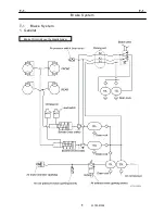
Brake (Service Brake)
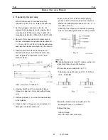
1.1 Principle of operation
1. When hydraulic pressure is applied
The pistons exert force to the pad assy by
deforming the piston seals. (Fig. 2)
2. When hydraulic pressure is removed
The seals recover the original shape to push the
pistons back, creating clearance between the disc
plate and the pad assy. (Fig. 3 )
3. When pad assy wears
The piston displacement distance increases
beyond the seal deformation limit, and the pistons
slip relative to the seals, but when the hydraulic
pressure is removed, the pistons are pulled back
by the seals through the same distance as before
the occurance of wear, giving the same
clearances.
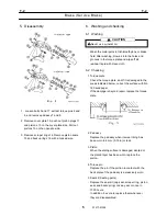
2. Checking the pad assy
[NOTICE]
The brake caliper must be disassembled to check
the remained pad thickness. However, the check
gauge may use to check.
The simple check method of pad assy is shown as
follows:
Check the pad thickness by inserting a check gauge
as shown below in the check holes in the torque
plate.
R
0.
2
C
0.5
IW577-017201
90
5
.5
9
60±0.2
[NOTICE]
When one of the pad assy is found to have worn to
the use limit, all the other ones are also worn to the
same limit in most cases.
Replace the pad assy for the right and the left
wheels or even for all the four wheels
simultaneously.
Thickness of the brake lining of the Pad assy
Thickness of the brake lining
New parts
14 mm (0.56in)
Use limit
4 mm (0.16in)
The regular check is necessary to prevent from
deteriorating brake function and from the brake
damage since the thickness of the brake lining
exceeding the limit results in serious damage.
Replace the pad assy when this
distance becomes zero.
Piston
Back plate
Pad assy
Brake lining
Disc plate
IW577-0190E02
Check gauge
3. Checking the disc plate
Check the disc plate for the thickness and
damage. If it is excessively damaged or the
thickness is below 17.5 mm (0.689 in), replace the
disc plate. (Thickness of new disc plate: 20 mm
(0.787 in))
(Unit: mm) (1mm=0.039inch)
Содержание TR-800XXL4
Страница 47: ...B 9 B 9 Rotary Joint 27 W181 0440E Upper view A Lower view B...
Страница 75: ...B 13 B 13 Solenoid Control Valve Jib Set 55 W112 0222E IW112 0220E05 P T C C IW112 0220E06 D D C O...
Страница 119: ...F 1 F 1 Winch System 1 WF02 0251E F 1 Winch System 1 General Hydraulic Circuit for Winch...
Страница 134: ...G 1 G 1 Telescoping System 2 WG02 0321E Boom Telescoping Auxiliary Hoist 545523 Remote Control Pressure Vent...
Страница 135: ...G 1 G 1 Telescoping System 3 WG02 0321E Telescoping cylinder at select...
Страница 143: ...G 2 G 2 Boom Five Section Boom G 2 11 W536 0761E 11...
Страница 196: ...13 13 W701 0220E K 2 K 2 Air Conditioner K 2 4 Layout 4 1 Overall layout 4 345 107 61000...
Страница 197: ...14 14 W701 0220E K 2 K 2 Air Conditioner K 2 4 2 Overall layout 0 345 110 73000...
Страница 198: ...15 15 W701 0220E K 2 K 2 Air Conditioner K 2 4 3 Evaporator section 5 345 107 02000...
Страница 199: ...16 W701 0220E K 2 K 2 Air Conditioner 5 Compressor Assy...
Страница 200: ...17 17 W701 0220E K 2 K 2 Air Conditioner K 2 6 Evaporator Assy...
Страница 201: ...18 18 W701 0220E K 2 K 2 Air Conditioner K 2 7 Condenser Assy...
Страница 202: ...19 19 W701 0220E K 2 K 2 Air Conditioner K 2 8 Electric 8 1 Electric circuit 0 363 205 60030...
Страница 203: ...20 20 W701 0220E K 2 K 2 Air Conditioner K 2 8 2 Main harness A...
Страница 204: ...21 21 W701 0220E K 2 K 2 Air Conditioner K 2 8 3 Main harness B...
Страница 221: ...38 K 2 K 2 K 2 Air Conditioner 38 W701 0220E 12 Compressor 12 1Compressor abnormal sound diagnosis chart...
Страница 222: ...39 K 2 K 2 K 2 Air Conditioner 39 W701 0220E 12 2Compressor diagnosis chart 1 2...
Страница 223: ...40 K 2 K 2 K 2 Air Conditioner 40 W701 0220E Compressor diagnosis chart 2 2...
Страница 224: ...K 2 K 2 Air Conditioner 41 W701 0220E 13 Troubleshooting...
Страница 225: ...K 2 K 2 Air Conditioner 42 W701 0220E...
Страница 226: ...K 2 K 2 Air Conditioner 43 W701 0220E...
Страница 227: ...K 2 K 2 Air Conditioner 44 W701 0220E...
Страница 228: ...K 2 K 2 Air Conditioner 45 W701 0220E...
Страница 229: ...K 2 K 2 Air Conditioner 46 W701 0220E...
Страница 236: ...L 1 L 1 Control System 1 WL02 0090E L 1 Control System 1 General of hydraulic pilot system Hydraulic Pilot Circuit...
Страница 237: ...L 1 L 1 Control System 2 WL02 0090E 2 General of pneumatic control devices Pneumatic Circuit...
Страница 266: ...T 1 T 1 Brake System 1 WT02 0120E T 1 Brake System 1 General Brake Circuit air over hydraulic brake...
Страница 291: ...T 5 T 5 Air Dryer 26 W232 0032E Heater View A 39 C B B A 58 59 2 IW232 0030E03...
Страница 365: ...Z 2 Z 2 Torque Converter Circuit Z 2 3 WZ05 0330E 3 Z 2 Torque Converter Circuit 0 347 411 60000...
Страница 366: ...Z 3 Z 3 Brake Circuit Pneumatic Circuit Z 3 4 WZ06 0410E 4 Z 3 Brake Circuit Pneumatic Circuit 0 347 411 50000...
Страница 370: ...8 8 WZ03 3300E Z 5 Z 5 Electric Circuit MDT Carrier Upper Z 5 IWZ03 3300E01...
Страница 372: ...10 Z 6 Z 6 Electric Circuit MDT Carrier Lower Z 6 10 WZ03 3310E IWZ03 3310E01...
Страница 382: ...Z 9 Z 9 Location of Air Parts 20 WZ08 0300E 2 Carrier Enlarge view of A center of the carrier s right hand...
Страница 387: ...25 Z 13 Z 13 Location of Air Parts AML Z 13 25 WZ02 3000E Z 13 Location of Air Parts AML 0 343 632 31000 0 343 632 81000...
Страница 394: ...Z 18 Z 18 Harness Swing Table Left Z 18 32 WZ04 2280E 32 Z 18 Harness Swing Table Left 1 343 536 22020...
Страница 395: ...Z 19 Z 19 Harness Swing Table Right Z 19 33 WZ04 2290E 33 Z 19 Harness Swing Table Right 1 343 536 22010...
Страница 396: ...Z 20 Z 20 Harness Boom Z 20 34 WZ04 2300E 34 Z 20 Harness Boom 0 343 536 22040 0 343 536 22030 Boom base Boom top...
Страница 397: ...Z 21 Z 21 Harness AML Upper Z 21 35 WZ04 2310E 35 Z 21 Harness AML Upper 1 343 632 31100 1 343 632 31200 1 343 632 31300...
Страница 400: ...38 Z 24 Z 24 Harness Lower Sub 38 WZ04 2450E Z 24 Z 24 Harness Lower Sub 2 349 310 00200...


