


Y - 1
Y - 1
Hydraulic Pressure Setting Table
1
WY02-0640E
Y-1
Hydraulic Pressure Setting Table
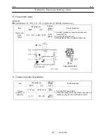
1. Winch
[NOTICE]
Oil temperature: 45 - 55°C (113 - 131°F) (Hydraulic oil: TADANO Hydraulic oil LL)
Confirm set pressure on AML (load moment indicator) moment display
Shift the elevation slow stop cancel switch to OFF side
Set pressure
Item
MPa psi
Engine
speed
(min
-1
)
Check procedure
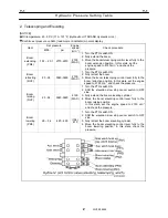
Main winch
hoisting up
(RV1)
Aux. winch
hoisting up
(RV1)
27 - 28
3910 - 4050
2150
(MAX.)
1. Place the main winch brake in the hold state. *1
2. Turn the PTO switch ON.
3. Move the main winch control lever fully to the hoist
up position while the boom elevating control lever
is fully moved to the boom lowering position. In this
state, set the engine speed to 2150 min
-1
and
check the pressure.
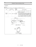
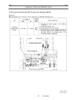
Aux. winch
hoisting
down
(PR1)
8.3 - 9.3
1210 - 1350
(IDL.)
670
1. Place the auxiliary winch brake in the hold state. *1
2. Turn the PTO switch ON.
3. Move the boom telescoping /auxiliary winch control
lever fully to the hoist down position while the boom
elevating control lever is fully moved to the boom
lowering position. In this state, check the pressure.
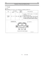
Main winch
hoisting
down
(PR2)
8.3 - 9.3
1210 - 1350
(IDL.)
670
1. Place the main winch brake in the hold state. *1
2. Turn the PTO switch ON.
3. Move the main winch control lever fully to the hoist
down position while the boom elevating control
lever is fully moved to the boom lowering position.
In this state, check the pressure.
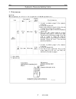
(*1): When the winch brake is in the hold state, the winch brake will not be released and winch drum will
not rotate by hoist up or hoist down operation. To have the winch brake placed in the hold state,
remove the pipes for the winch brake release to the hydraulic motor for winch. The pilot pressure for
the winch brake release will be produced during the hoist up or hoist down operation, therefore, fit on
the cap to avoid the oil leak. (After checking the pressure, return the pipes to the original position and
bleed the winch brake release circuit.)
Содержание TR-800XXL4
Страница 47: ...B 9 B 9 Rotary Joint 27 W181 0440E Upper view A Lower view B...
Страница 75: ...B 13 B 13 Solenoid Control Valve Jib Set 55 W112 0222E IW112 0220E05 P T C C IW112 0220E06 D D C O...
Страница 119: ...F 1 F 1 Winch System 1 WF02 0251E F 1 Winch System 1 General Hydraulic Circuit for Winch...
Страница 134: ...G 1 G 1 Telescoping System 2 WG02 0321E Boom Telescoping Auxiliary Hoist 545523 Remote Control Pressure Vent...
Страница 135: ...G 1 G 1 Telescoping System 3 WG02 0321E Telescoping cylinder at select...
Страница 143: ...G 2 G 2 Boom Five Section Boom G 2 11 W536 0761E 11...
Страница 196: ...13 13 W701 0220E K 2 K 2 Air Conditioner K 2 4 Layout 4 1 Overall layout 4 345 107 61000...
Страница 197: ...14 14 W701 0220E K 2 K 2 Air Conditioner K 2 4 2 Overall layout 0 345 110 73000...
Страница 198: ...15 15 W701 0220E K 2 K 2 Air Conditioner K 2 4 3 Evaporator section 5 345 107 02000...
Страница 199: ...16 W701 0220E K 2 K 2 Air Conditioner 5 Compressor Assy...
Страница 200: ...17 17 W701 0220E K 2 K 2 Air Conditioner K 2 6 Evaporator Assy...
Страница 201: ...18 18 W701 0220E K 2 K 2 Air Conditioner K 2 7 Condenser Assy...
Страница 202: ...19 19 W701 0220E K 2 K 2 Air Conditioner K 2 8 Electric 8 1 Electric circuit 0 363 205 60030...
Страница 203: ...20 20 W701 0220E K 2 K 2 Air Conditioner K 2 8 2 Main harness A...
Страница 204: ...21 21 W701 0220E K 2 K 2 Air Conditioner K 2 8 3 Main harness B...
Страница 221: ...38 K 2 K 2 K 2 Air Conditioner 38 W701 0220E 12 Compressor 12 1Compressor abnormal sound diagnosis chart...
Страница 222: ...39 K 2 K 2 K 2 Air Conditioner 39 W701 0220E 12 2Compressor diagnosis chart 1 2...
Страница 223: ...40 K 2 K 2 K 2 Air Conditioner 40 W701 0220E Compressor diagnosis chart 2 2...
Страница 224: ...K 2 K 2 Air Conditioner 41 W701 0220E 13 Troubleshooting...
Страница 225: ...K 2 K 2 Air Conditioner 42 W701 0220E...
Страница 226: ...K 2 K 2 Air Conditioner 43 W701 0220E...
Страница 227: ...K 2 K 2 Air Conditioner 44 W701 0220E...
Страница 228: ...K 2 K 2 Air Conditioner 45 W701 0220E...
Страница 229: ...K 2 K 2 Air Conditioner 46 W701 0220E...
Страница 236: ...L 1 L 1 Control System 1 WL02 0090E L 1 Control System 1 General of hydraulic pilot system Hydraulic Pilot Circuit...
Страница 237: ...L 1 L 1 Control System 2 WL02 0090E 2 General of pneumatic control devices Pneumatic Circuit...
Страница 266: ...T 1 T 1 Brake System 1 WT02 0120E T 1 Brake System 1 General Brake Circuit air over hydraulic brake...
Страница 291: ...T 5 T 5 Air Dryer 26 W232 0032E Heater View A 39 C B B A 58 59 2 IW232 0030E03...
Страница 365: ...Z 2 Z 2 Torque Converter Circuit Z 2 3 WZ05 0330E 3 Z 2 Torque Converter Circuit 0 347 411 60000...
Страница 366: ...Z 3 Z 3 Brake Circuit Pneumatic Circuit Z 3 4 WZ06 0410E 4 Z 3 Brake Circuit Pneumatic Circuit 0 347 411 50000...
Страница 370: ...8 8 WZ03 3300E Z 5 Z 5 Electric Circuit MDT Carrier Upper Z 5 IWZ03 3300E01...
Страница 372: ...10 Z 6 Z 6 Electric Circuit MDT Carrier Lower Z 6 10 WZ03 3310E IWZ03 3310E01...
Страница 382: ...Z 9 Z 9 Location of Air Parts 20 WZ08 0300E 2 Carrier Enlarge view of A center of the carrier s right hand...
Страница 387: ...25 Z 13 Z 13 Location of Air Parts AML Z 13 25 WZ02 3000E Z 13 Location of Air Parts AML 0 343 632 31000 0 343 632 81000...
Страница 394: ...Z 18 Z 18 Harness Swing Table Left Z 18 32 WZ04 2280E 32 Z 18 Harness Swing Table Left 1 343 536 22020...
Страница 395: ...Z 19 Z 19 Harness Swing Table Right Z 19 33 WZ04 2290E 33 Z 19 Harness Swing Table Right 1 343 536 22010...
Страница 396: ...Z 20 Z 20 Harness Boom Z 20 34 WZ04 2300E 34 Z 20 Harness Boom 0 343 536 22040 0 343 536 22030 Boom base Boom top...
Страница 397: ...Z 21 Z 21 Harness AML Upper Z 21 35 WZ04 2310E 35 Z 21 Harness AML Upper 1 343 632 31100 1 343 632 31200 1 343 632 31300...
Страница 400: ...38 Z 24 Z 24 Harness Lower Sub 38 WZ04 2450E Z 24 Z 24 Harness Lower Sub 2 349 310 00200...


