


26
W701-0220E
K - 2
K - 2
Air Conditioner
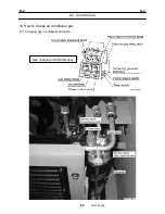
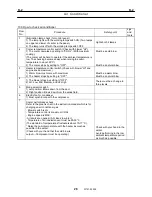
10.2 How to charge air conditioner gas
Flow
No.
Procedure Safety
point
Jigs and
tools
1
Plug the power supply cord of the main unit.
2
Connect the coupler of the high-pressure side (red hose) and the
low-pressure side with the compressor main body sequentially.
Purge residual pressure before connecting because the
connection of coupler becomes firm if there is residual pressure in
the unit.
(Usually it has been performed at work end. Refer to Flow No.16.)
Be careful to the
scaffold
3
Attach one freon can.
(Put the blind caps to the couplers which gas-can has not been
attached.)
Tighten as it is though the gas leaks a little when attaching.
Be careful that gas
liquor does not splash
4
Set the time switch to the position of gas replenishment.
5
Turns the power switch to the manual side. (with 3 seconds
automatic air purge)
6
Start the engine.
- Engine speed: Idling
- Temperature control: Maximum cool
- Blower: Lo-Hi
Make sure to check
surroundings
7
Check the condition of bubble in the sight glass. (Check whether
the bubble disappears.)
Make sure to check
surroundings
8
Turn OFF the power switch when the gas disappears from the
remainder gas sight glass of the main unit.
Be careful to the
scaffold
9
Detach the empty gas can, and attach another gas can.
Be careful that gas
liquor does not splash
10
Turns the power switch to the manual side. (with 3 seconds
automatic air purge)
- Repeat Flow No.7 until the bubble disappears.
(The charging amount should be 200g
±
50g after the bubble
disappears.)
11
Turn OFF the power switch when the gas disappears from the
remainder gas sight glass of the main unit.
12
Check the air-conditioning capability
Temperature control: : Maximum cool
Blower: : Hi
Engine speed : Approx. 2000 rpm
The blowing temperature must be in the graphic chart value.
(Refer to the graphic chart.)
(Near the outside air temperature scale in the gauge is a standard
pressure.)
13
Stop the engine
Pull out the key
14
Wait for two minutes until pressure falls, and detach the
high-pressure side and low-pressure side quick couplers.
Be careful to the
scaffold
15
Test gas leakage. (for all hose connections)
(Check the gas leakage from the lower side because the freon is
heavier than air.)
Compressor: 2 places
Compressor charge coupler: 2 places
Receiver: 2 places
Condenser Assy: 2 places
Main body of air conditioner: 2 places
Pressure switch hose connections : 1 place
11 places in total
Be careful to the
scaffold
Gas
leak
tester
Содержание TR-800XXL4
Страница 47: ...B 9 B 9 Rotary Joint 27 W181 0440E Upper view A Lower view B...
Страница 75: ...B 13 B 13 Solenoid Control Valve Jib Set 55 W112 0222E IW112 0220E05 P T C C IW112 0220E06 D D C O...
Страница 119: ...F 1 F 1 Winch System 1 WF02 0251E F 1 Winch System 1 General Hydraulic Circuit for Winch...
Страница 134: ...G 1 G 1 Telescoping System 2 WG02 0321E Boom Telescoping Auxiliary Hoist 545523 Remote Control Pressure Vent...
Страница 135: ...G 1 G 1 Telescoping System 3 WG02 0321E Telescoping cylinder at select...
Страница 143: ...G 2 G 2 Boom Five Section Boom G 2 11 W536 0761E 11...
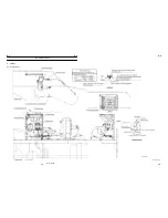
Страница 196: ...13 13 W701 0220E K 2 K 2 Air Conditioner K 2 4 Layout 4 1 Overall layout 4 345 107 61000...
Страница 197: ...14 14 W701 0220E K 2 K 2 Air Conditioner K 2 4 2 Overall layout 0 345 110 73000...
Страница 198: ...15 15 W701 0220E K 2 K 2 Air Conditioner K 2 4 3 Evaporator section 5 345 107 02000...
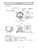
Страница 199: ...16 W701 0220E K 2 K 2 Air Conditioner 5 Compressor Assy...
Страница 200: ...17 17 W701 0220E K 2 K 2 Air Conditioner K 2 6 Evaporator Assy...
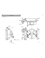
Страница 201: ...18 18 W701 0220E K 2 K 2 Air Conditioner K 2 7 Condenser Assy...
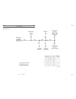
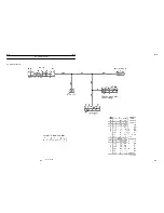
Страница 202: ...19 19 W701 0220E K 2 K 2 Air Conditioner K 2 8 Electric 8 1 Electric circuit 0 363 205 60030...
Страница 203: ...20 20 W701 0220E K 2 K 2 Air Conditioner K 2 8 2 Main harness A...
Страница 204: ...21 21 W701 0220E K 2 K 2 Air Conditioner K 2 8 3 Main harness B...
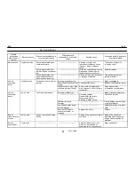
Страница 221: ...38 K 2 K 2 K 2 Air Conditioner 38 W701 0220E 12 Compressor 12 1Compressor abnormal sound diagnosis chart...
Страница 222: ...39 K 2 K 2 K 2 Air Conditioner 39 W701 0220E 12 2Compressor diagnosis chart 1 2...
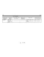
Страница 223: ...40 K 2 K 2 K 2 Air Conditioner 40 W701 0220E Compressor diagnosis chart 2 2...
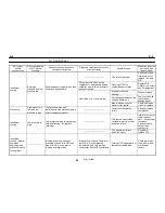
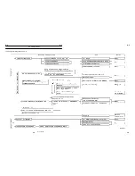
Страница 224: ...K 2 K 2 Air Conditioner 41 W701 0220E 13 Troubleshooting...
Страница 225: ...K 2 K 2 Air Conditioner 42 W701 0220E...
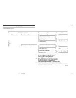
Страница 226: ...K 2 K 2 Air Conditioner 43 W701 0220E...
Страница 227: ...K 2 K 2 Air Conditioner 44 W701 0220E...
Страница 228: ...K 2 K 2 Air Conditioner 45 W701 0220E...
Страница 229: ...K 2 K 2 Air Conditioner 46 W701 0220E...
Страница 236: ...L 1 L 1 Control System 1 WL02 0090E L 1 Control System 1 General of hydraulic pilot system Hydraulic Pilot Circuit...
Страница 237: ...L 1 L 1 Control System 2 WL02 0090E 2 General of pneumatic control devices Pneumatic Circuit...
Страница 266: ...T 1 T 1 Brake System 1 WT02 0120E T 1 Brake System 1 General Brake Circuit air over hydraulic brake...
Страница 291: ...T 5 T 5 Air Dryer 26 W232 0032E Heater View A 39 C B B A 58 59 2 IW232 0030E03...
Страница 365: ...Z 2 Z 2 Torque Converter Circuit Z 2 3 WZ05 0330E 3 Z 2 Torque Converter Circuit 0 347 411 60000...
Страница 366: ...Z 3 Z 3 Brake Circuit Pneumatic Circuit Z 3 4 WZ06 0410E 4 Z 3 Brake Circuit Pneumatic Circuit 0 347 411 50000...
Страница 370: ...8 8 WZ03 3300E Z 5 Z 5 Electric Circuit MDT Carrier Upper Z 5 IWZ03 3300E01...
Страница 372: ...10 Z 6 Z 6 Electric Circuit MDT Carrier Lower Z 6 10 WZ03 3310E IWZ03 3310E01...
Страница 382: ...Z 9 Z 9 Location of Air Parts 20 WZ08 0300E 2 Carrier Enlarge view of A center of the carrier s right hand...
Страница 387: ...25 Z 13 Z 13 Location of Air Parts AML Z 13 25 WZ02 3000E Z 13 Location of Air Parts AML 0 343 632 31000 0 343 632 81000...
Страница 394: ...Z 18 Z 18 Harness Swing Table Left Z 18 32 WZ04 2280E 32 Z 18 Harness Swing Table Left 1 343 536 22020...
Страница 395: ...Z 19 Z 19 Harness Swing Table Right Z 19 33 WZ04 2290E 33 Z 19 Harness Swing Table Right 1 343 536 22010...
Страница 396: ...Z 20 Z 20 Harness Boom Z 20 34 WZ04 2300E 34 Z 20 Harness Boom 0 343 536 22040 0 343 536 22030 Boom base Boom top...
Страница 397: ...Z 21 Z 21 Harness AML Upper Z 21 35 WZ04 2310E 35 Z 21 Harness AML Upper 1 343 632 31100 1 343 632 31200 1 343 632 31300...
Страница 400: ...38 Z 24 Z 24 Harness Lower Sub 38 WZ04 2450E Z 24 Z 24 Harness Lower Sub 2 349 310 00200...


