


Y - 5
Y - 5
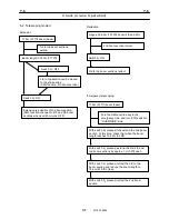
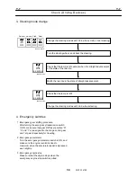
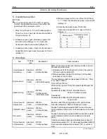
Adjustment and Checks
20
WY05-1390E
Y-5
Adjustment and Checks
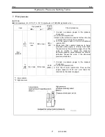
1. Service brake adjustment
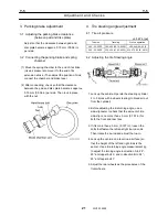
1.1 Adjusting the brake pedal
With the pedal weight causing the roller to contact
the plunger, adjust the bolt until it contacts the
stopper, then use the nut to lock it in place.
IWY05-0141E10
Plunger
Bolt
Nut
Roller
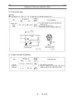
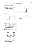
1.2 Tightening the cap of reserve tank of service
brake fluid
After bleeding air, pour the brake fluid up to a
required level, and tighten the cap until it stops at
the stopper. At this time, the position of tank body
and cap should be as shown in Fig.1. In addition,
tighten the cap until the mark is aligned with the
mark on tank as shown in Fig.2.
The stopper might be broken when tightening the
cap too much.
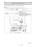
2. Accelerator adjustment
2.1 Accelerator pedal
IWY05-0141E07
Switch
(Idle volume)
Idling
MAX
A
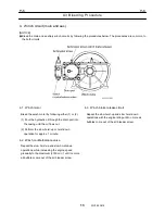
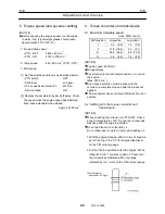
1. Adjust bolt F so that lever I is vertical, then lock
the bolt with the nut.
IWY05-0141E08
Lever I
Bolt F
Bolt E
Nut H
Viewed from A
[NOTICE]
Be sure to check that the idle SW operates reliably.
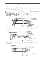
2. Move the accelerator sensor lever so that it
contacts stopper C. Then adjust nut H until there
is no pedal play.
IWY05-0141E09
Stopper D
Apply grease
Lever
Stopper C
(Idle SW)
3. When at Max. position (accelerator sensor lever in
contact with stopper D), place bolt E in contact
with the lever on the underside of the pedal, and
lock in place with the nut.
Содержание TR-800XXL4
Страница 47: ...B 9 B 9 Rotary Joint 27 W181 0440E Upper view A Lower view B...
Страница 75: ...B 13 B 13 Solenoid Control Valve Jib Set 55 W112 0222E IW112 0220E05 P T C C IW112 0220E06 D D C O...
Страница 119: ...F 1 F 1 Winch System 1 WF02 0251E F 1 Winch System 1 General Hydraulic Circuit for Winch...
Страница 134: ...G 1 G 1 Telescoping System 2 WG02 0321E Boom Telescoping Auxiliary Hoist 545523 Remote Control Pressure Vent...
Страница 135: ...G 1 G 1 Telescoping System 3 WG02 0321E Telescoping cylinder at select...
Страница 143: ...G 2 G 2 Boom Five Section Boom G 2 11 W536 0761E 11...
Страница 196: ...13 13 W701 0220E K 2 K 2 Air Conditioner K 2 4 Layout 4 1 Overall layout 4 345 107 61000...
Страница 197: ...14 14 W701 0220E K 2 K 2 Air Conditioner K 2 4 2 Overall layout 0 345 110 73000...
Страница 198: ...15 15 W701 0220E K 2 K 2 Air Conditioner K 2 4 3 Evaporator section 5 345 107 02000...
Страница 199: ...16 W701 0220E K 2 K 2 Air Conditioner 5 Compressor Assy...
Страница 200: ...17 17 W701 0220E K 2 K 2 Air Conditioner K 2 6 Evaporator Assy...
Страница 201: ...18 18 W701 0220E K 2 K 2 Air Conditioner K 2 7 Condenser Assy...
Страница 202: ...19 19 W701 0220E K 2 K 2 Air Conditioner K 2 8 Electric 8 1 Electric circuit 0 363 205 60030...
Страница 203: ...20 20 W701 0220E K 2 K 2 Air Conditioner K 2 8 2 Main harness A...
Страница 204: ...21 21 W701 0220E K 2 K 2 Air Conditioner K 2 8 3 Main harness B...
Страница 221: ...38 K 2 K 2 K 2 Air Conditioner 38 W701 0220E 12 Compressor 12 1Compressor abnormal sound diagnosis chart...
Страница 222: ...39 K 2 K 2 K 2 Air Conditioner 39 W701 0220E 12 2Compressor diagnosis chart 1 2...
Страница 223: ...40 K 2 K 2 K 2 Air Conditioner 40 W701 0220E Compressor diagnosis chart 2 2...
Страница 224: ...K 2 K 2 Air Conditioner 41 W701 0220E 13 Troubleshooting...
Страница 225: ...K 2 K 2 Air Conditioner 42 W701 0220E...
Страница 226: ...K 2 K 2 Air Conditioner 43 W701 0220E...
Страница 227: ...K 2 K 2 Air Conditioner 44 W701 0220E...
Страница 228: ...K 2 K 2 Air Conditioner 45 W701 0220E...
Страница 229: ...K 2 K 2 Air Conditioner 46 W701 0220E...
Страница 236: ...L 1 L 1 Control System 1 WL02 0090E L 1 Control System 1 General of hydraulic pilot system Hydraulic Pilot Circuit...
Страница 237: ...L 1 L 1 Control System 2 WL02 0090E 2 General of pneumatic control devices Pneumatic Circuit...
Страница 266: ...T 1 T 1 Brake System 1 WT02 0120E T 1 Brake System 1 General Brake Circuit air over hydraulic brake...
Страница 291: ...T 5 T 5 Air Dryer 26 W232 0032E Heater View A 39 C B B A 58 59 2 IW232 0030E03...
Страница 365: ...Z 2 Z 2 Torque Converter Circuit Z 2 3 WZ05 0330E 3 Z 2 Torque Converter Circuit 0 347 411 60000...
Страница 366: ...Z 3 Z 3 Brake Circuit Pneumatic Circuit Z 3 4 WZ06 0410E 4 Z 3 Brake Circuit Pneumatic Circuit 0 347 411 50000...
Страница 370: ...8 8 WZ03 3300E Z 5 Z 5 Electric Circuit MDT Carrier Upper Z 5 IWZ03 3300E01...
Страница 372: ...10 Z 6 Z 6 Electric Circuit MDT Carrier Lower Z 6 10 WZ03 3310E IWZ03 3310E01...
Страница 382: ...Z 9 Z 9 Location of Air Parts 20 WZ08 0300E 2 Carrier Enlarge view of A center of the carrier s right hand...
Страница 387: ...25 Z 13 Z 13 Location of Air Parts AML Z 13 25 WZ02 3000E Z 13 Location of Air Parts AML 0 343 632 31000 0 343 632 81000...
Страница 394: ...Z 18 Z 18 Harness Swing Table Left Z 18 32 WZ04 2280E 32 Z 18 Harness Swing Table Left 1 343 536 22020...
Страница 395: ...Z 19 Z 19 Harness Swing Table Right Z 19 33 WZ04 2290E 33 Z 19 Harness Swing Table Right 1 343 536 22010...
Страница 396: ...Z 20 Z 20 Harness Boom Z 20 34 WZ04 2300E 34 Z 20 Harness Boom 0 343 536 22040 0 343 536 22030 Boom base Boom top...
Страница 397: ...Z 21 Z 21 Harness AML Upper Z 21 35 WZ04 2310E 35 Z 21 Harness AML Upper 1 343 632 31100 1 343 632 31200 1 343 632 31300...
Страница 400: ...38 Z 24 Z 24 Harness Lower Sub 38 WZ04 2450E Z 24 Z 24 Harness Lower Sub 2 349 310 00200...


