5.3
Mains connection
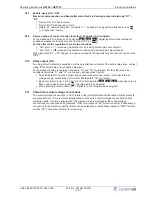
Power from the mains is connected to terminals: PE, L1 and N. Here, it must be strictly observed that
the mains voltage lies within the allowable tolerance speci
fi
cations (
Technical data and nameplate
af
fi
xed to the side).
Danger due to electric current
The mains voltage must comply with the DIN EN 50160 quality characteristics and the de
fi
ned
standard voltages in IEC 60038!
5.4
Motor connection
The motor is connected at terminals U1 and U2. Several motors can be connected to the device.
Attention
The maximum total control current (speci
fi
ed for electronic voltage regulation) for all motors
may not exceed the device
’
s rated current.
If the maximum control current for electronic voltage regulation is not known, a supplementary
20% of the rated motor current must be allowed for.
When controlling motors from other manufacturers, the controllability and the maximum
current for electronic voltage regulation should be requested from the manufacturer.
Information
It is recommended that a separate motor protection unit be foreseen for each fan.
5.4.1
Running noise
When controlling ventilators using electronic voltage regulators, motor noise can occur (due to the
system), which can be troublesome.
On fast running ventilators with a high level of air noise, this noise is relatively low. On slow running
ventilators with a low level of air noise, this noise may be dominant in the lower speed range due to
the occurrence of resonance.
5.5
Motor protection
The motor can be protected by connecting thermostats
“
TB
”
.
When multiple motors are connected, it is essential to ensure that thermostats
“
TB
”
are always
connected in series.
If a connected thermostat is tripped (break between the two terminals
“
TB
”
), the device is switched off
and is not switched back on.
Relais
“
K1
”
is de-energized, terminals
“
11
”
-
“
12
”
bridged. The signal lamp
fl
ashes in code
|
2
|
(
Diagnostics / faults).
Possibilities for re-starting after the drive has cooled down (terminals
“
TB
”
bridged) by:
•
By switching the mains voltage off and then on again.
•
Via a digital input for remote control (ON / OFF enable).
Attention!
•
An outside voltage may never be connected to the terminals
“
TB
”
!
•
If a bypass circuit is installed, or in the
“
100 %
”
position on devices with a main switch, the motor
protection inside the controller has no function. In this case, additional motor monitoring may be
required.
5.6
Signal or sensor connection (E1 = Analog In 1)
The unit has one-analog input: terminals
“
E1
”
/
“
GND
”
(Analog In 1).
The connection is independent of the programmed operating mode and from the sensor signal
employed.
The internal jumpers must be placed in correct position depending on input signal. Factory setting 0 -
10 V.
•
When connecting
passive
temperature sensors TF.. (KTY81-210) must be paid attention to no
polarity.
•
When connecting
active
sensors attention must be paid to correct polarity, a 24 V DC power
supply is integrated.
Operating Instructions
RETP6 / RETP10
Electrical installation
L-BAL-E082-GB 1237 Index 002
Part.-No. 00163339-GB
9/31


