6.2
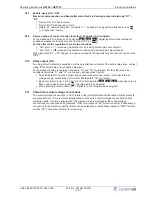
Internal Setting
Attention!
The controller housing cover may only be removed when the power line has been switched off!
It is generally forbidden to carry out work on electrical live parts. Protection class of the device when
open is IP 00! It is possible to touch hazardous voltages directly!
19.09.2008
v_pxet_q_intern_bed.VSD
%
n-max
0
100
R
7
%
set
0
100
R4
R5
%
n-min
0
100
R6
V
°C
mA
E1
ON
OFF
10
9
8
7
6
5
4
3
2
1
DIP S1
%
Pband
5
30
Potentiometer
set
For main switch position
“
Auto
”
function depending on internal switch DIP 2 and selected mode (for
main switch position
“
Hand
”
without function).
•
For
Speed controller
1.01
and DIP 2 =
|
OFF
|
(factory setting) without function
•
For
Speed controller
1.01
and DIP 2 =
|
ON
|
setting of output voltage 0 - 100 %
For
P-Controller
,
2.01
,
3.01
and
PI-Controller
,
4.01
can be selected with DIP 2 whether setpoint
setting is made by these internal potentiometer or by the outside potentiometer, (factory setting
internal potentiometer active (DIP 2 =
|
OFF
|
).
•
For
temperature control
2.01
with passive sensors TF.. (KTY).
setting range: 0 - 100 %
-26...76
°
C (measuring range of controller).
•
For
control with active sensors
3.01
,
4.01
(0 - 10 V, 4 - 20 mA).
Setting range: 0 - 100 %
measuring range of sensor.
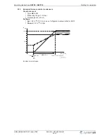
Potentiometer
Pband
Function dependently on selected mode of operation
•
For
Speed controller
1.01
: without function
•
P-controller
2.01
,
3.01
–
For
temperature control with passive sensors TF.. (KTY).
Setting range: 5 - 30 %
5.1 - 30.6 K.
–
For
control with active sensors (0 - 10 V, 4 - 20 mA).
Setting range: 5 - 30 %
5 - 30 % measuring range of sensor.
•
PI-Controllerr
4.01
–
For
control with active sensors (0 - 10 V, 4 - 20 mA).
Setting range: 5 - 30 %
5 - 100 % measuring range of sensor.
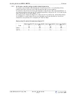
Potentiometer
n-min
Minimal output voltage (basic speed)
Setting range: 0 - 100 % (
“
n-min
”
takes priority if over
“
n-max
”
)
Potentiometer
n-max
Maximal output voltage (speed limiter)
Setting range: 100 % -
“
n-min
”
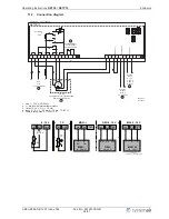
Jumper
E1
Basic setting for kind of signal at analog input
“
E1 = Analog In 1
”
Dipswitch
S1
Basic setting for device function
Operating Instructions
RETP6 / RETP10
Operating and display elements
L-BAL-E082-GB 1237 Index 002
Part.-No. 00163339-GB
13/31


