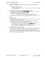
7.3
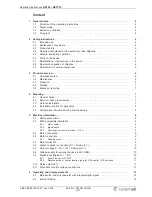
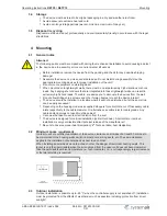
Function of dipswitches for operation as Speed controller
1.01
(DIP 1 =
|
OFF
|
)
For operation as a speed controller (main switch = Auto), the output voltage is set manually by
adjusting the built-in potentiometer, by an external potentiometer or external signal.
The desired function is determined with dipswitch
S1
.
Position factory setting for all dipswitches =
|
OFF
|
DIP
Function
OFF
ON
1
Selection:
Speed controller / P-Controller,
PI-Controller
Speed controller
P-Controller, PI-controller
2
Signal source of control
Setting of output voltage by external signal
to
“
E1
”
(
“
Potentiometer outside
”
and
“
potentiome-
ter inside
”
=
“
set
”
without function)
Setting of output voltage by
“
potentiometer
inside
”
=
“
set
”
(
“
Potentiometer outside
”
without function)
3
Type of Signal
0 - 10 V, 0 - 20 mA
2 - 10 V, 4 - 20 mA
4
Inverting signal input
0 - 10 V, 2 - 10 V, 0 - 20 mA, 4 - 20 mA
10 - 0 V, 10 - 2 V, 20 - 0 mA, 20 - 4 mA
5
Minimum speed cut off
OFF
ON
6
Hardstart function
OFF
ON
7
no function
-
-
8
Function signal output
“
Analog
Out 1
”
Constant voltage
“
+ 10 V
”
for external
potentiometer
0 - 10 V
modulation 0 - 100 %
9
no function
-
-
10
no function
-
-
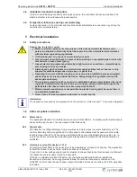
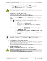
7.4
Function of dipswitches for operation as P-Controller, PI-Controller,
2.01
,
3.01
,
4.01
(DIP 1 =
|
ON
|
)
For operation as a P-controller, PI-Controller (main switch = Auto) the actual value measured by the
sensor is compared with the nominal value that has been set. The output voltage and hence the
rotational speed of the connected motor automatically change as a function of the parameter settings.
The desired function is determined with dipswitch
S1
.
Position factory setting for all dipswitches =
|
OFF
|
DIP
Function
OFF
ON
1
Selection:
Speed controller / P-Controller,
PI-Controller
Speed controller
P-Controller, PI-controller
2
Function
“
potentiometer out-
side
”
Setpoint setting via
“
potentiometer inside
”
=
“
set
”
.
“
Potentiometer outside
”
without function.
Setpoint setting via
“
potentiometer out-
side
”
“
Potentiometer inside
”
=
“
set
”
without func-
tion.
3
Type of Signal
0 - 10 V, 0 - 20 mA
TF.. (KTY)
2 - 10 V, 4 - 20 mA
4
Control function (e.g.
“
Cooling
”
/
“
Heating
”
increasing modulation for increasing actual
value
increasing modulation for decreasing ac-
tual value
5
Minimum speed cut off
OFF
ON
6
Hardstart function
OFF
ON
7
Controller function
|
P
|
Applications:
Temperature control airconditioning and
refrigeration
“
sensor TF..
”
Pressure control condensers (refrigera-
tion)
“
sensor MBG..
”
|
PI
|
Applications:
Volume control (constant) for ventilation
systems
“
Sensor DSG..
”
Air velocity control e.g. clean room
“
Sensor
MAL..
”
8
Function digital input
“
Digital In
1
”
Enable
Device ON / OFF
Switch over control function:
- Val > Set = n+ (Cooling)
- Val < Set = n+ (Heating)
(reverse function DIP 4)
9
no function
-
-
10
no function
-
-
Operating Instructions
RETP6 / RETP10
Base setup
L-BAL-E082-GB 1237 Index 002
Part.-No. 00163339-GB
15/31


