6
Operating and display elements
6.1
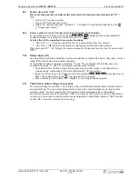
Main switch and potentiometer with integrated light signal
1
2
3
17.09.2012
v_retp_front_bed.VSD
1
Main switch
Position
Function
100 %
Ventilators are operated directly from the mains with no control.
The fuse in the device is bypassed! Motor protection has no function
0
Controller off
Auto
Function dependently on selected mode of operation
For
Speed controller
1.01
adjusting via external signal (DIP 2 =
|
OFF
|
= factory setting) or internal
potentiometer
“
set
”
(DIP 2 =
|
ON
|
).
Setting range: Output voltage 0 - 100 %.
For
P-Controller
,
2.01
,
3.01
and
PI-Controller
,
4.01
Automatic speed control depending on actual value measured and con
fi
gured set value.
Manual setting of output voltage by potentiometer 2
2
Potentiometer outside 0...100 %
For main switch position
“
Auto
”
function depending on internal switch
“
DIP 2
”
and selected mode
•
For
Speed controller
1.01
always without function
•
For the
P controller
,
2.01
,
3.01
and
PI controller
,
4.01
the
“
DIP 2
”
switch can be used to select whether
the set value setting can be made easily using the outer potentiometer or using the internal potentiometer
“
set
”
.
The internal potentiometer is set to active
ex-factory (DIP 2 =
|
OFF
|
) i.e. the set value setting is protected against unauthorized adjustments.
–
For
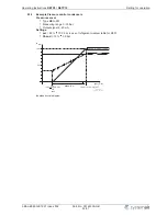
temperature control
2.01
with passive sensors TF.. (KTY).
setting range: 0 - 100 %
-26...76
°
C (measuring range of controller).
–
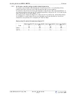
For
control with active sensors
3.01
,
4.01
(0 - 10 V, 4 - 20 mA).
Setting range: 0 - 100 %
measuring range of sensor.
For main switch position
“
Hand
”
•
Setting of output voltage 0 -100 %. Independently from input signal and selected mode.
3
Potentiometer with integrated light signal
Indicate the operating conditions over
fl
ashing code.
Operating Instructions
RETP6 / RETP10
Operating and display elements
L-BAL-E082-GB 1237 Index 002
Part.-No. 00163339-GB
12/31


