


FAAST 7100X
INSTALLATION AND MAINTENANCE INSTRUCTIONS
© Pertronic Industries Ltd
4
FAAST XS (7100X) Installation Guide Iss 1.0, 201606
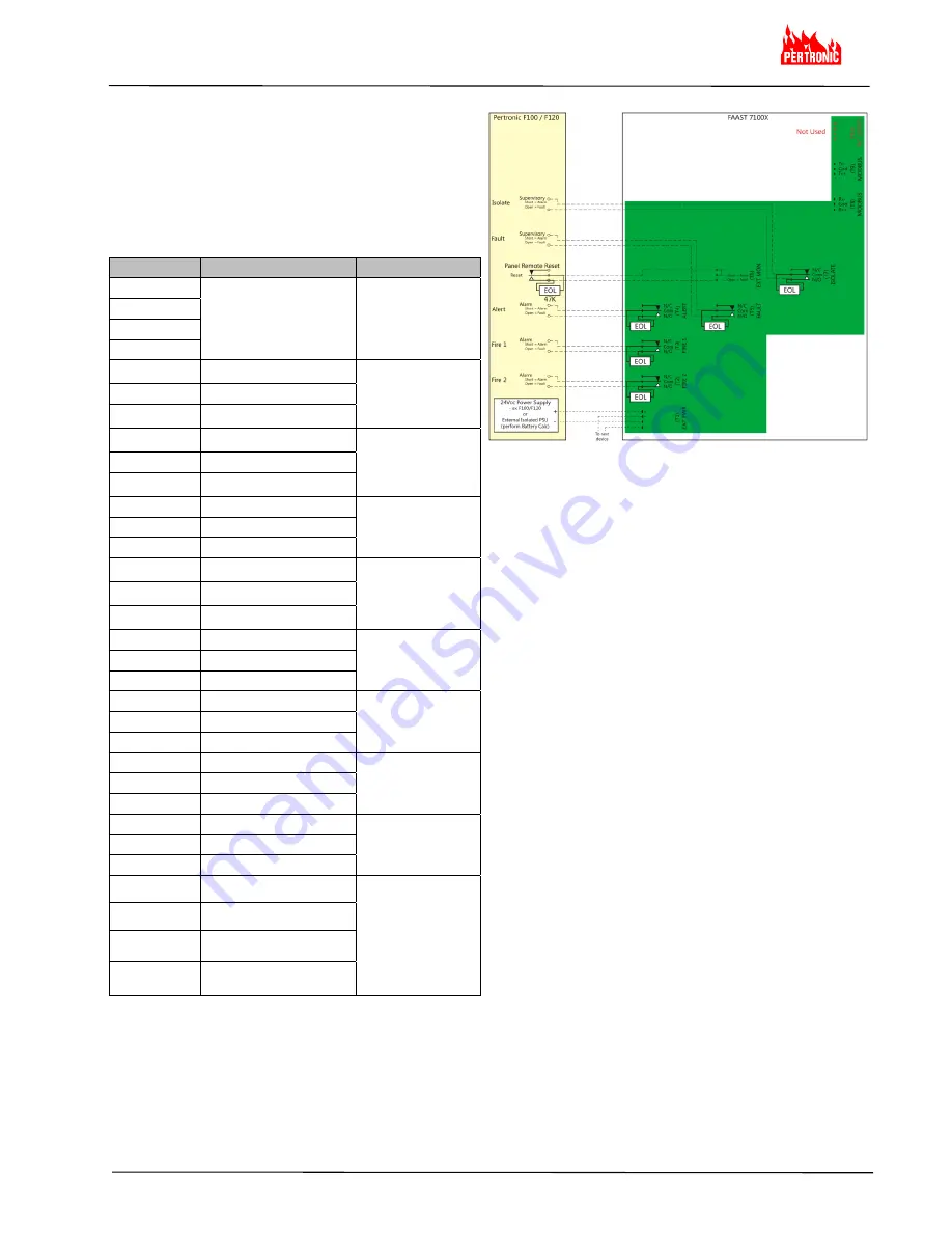
FAAST 7100X to FACP Wiring Diagram
Table 1b: FAAST 7100X Terminal Designations
Notes:
a) the Terminal Blocks are numbered with T10 to the top
and T1 at the bottom
b) the relays (T2 to T6) maintain their state on power loss
c) MODBUS RS485 Rx and Tx may be wired in Half-
Duplex configuration
d) Terminal Block T10 is unused
Number
Name
Terminal Block
32
SLC (Loop)
- Unused
T10
31
30
29
28
ModBus RS485 Tx
-
T9
27
ModBus COM
26
ModBus RS485 Tx
+
25
ModBus RS485 Rx
-
T8
24 ModBus
COM
23
ModBus RS485 Rx
+
22 Isolate
N/O
T7
21 Isolate
COM
20 Isolate
N/C
19
External Monitor
+
T6
18
External Monitor
-
17
External Monitor
-
16 Fault
N/O
T5
15 Fault
COM
14 Fault
N/C
13 Alert
N/C
T4
12 Alert
COM
11 Alert
N/O
10
Fire 1 N/C
T3
9
Fire 1 COM
8
Fire 1 N/O
7
Fire 2 N/C
T2
6
Fire 2 COM
5
Fire 2 N/O
4
External Power
+
T1
3
External Power
+
2
External Power
-
1
External Power
-
FAAST 7100X Cabling Requirements
The FAAST 7100X provides a series of Euro style
pluggable terminals, located behind the door on the
upper left side of the unit.
Refer to Table 1b for the proper electrical connections to
the unit and Figure 4b for typical connection for
monitoring a Stand-Alone FAAST system at a Fire
Alarm Control Panel (FACP).
Figure 4b: 7100X to FACP Wiring Diagram
FAAST 7100X System Powering
The following procedure describes how to initially power
up the FAAST system.
1. Unplug the unit’s power connector to the unit
before turning the power ON.
2. Turn the power ON.
3. Check the voltage at the connector - ensure it is
within the required voltage range.
4. If the voltage is within the proper range, reconnect
the power connector to the unit.
5. Connect a computer, with the PipeIQ software
installed, to the unit using either the USB or
Ethernet connections located above the
connectors
6. Use PipeIQ to upload the configuration previously
designed for the project.
7. The PC may be disconnected unless a permanent
networked connection is required
8. Verify the system fan starts up and air begins to
flow out of the exhaust port. The User Interface
provides the device status.
9. The device establishes an AirFlow BaseLine
during the first five (5) minutes of operation. After
five minutes, the AirFlow display provides the true
measured AirFlow status. The device provides
visual indication of the BaseLining period on the
LCD screen.
10. Connect the Remote Reset or 47K EOL across the
External Monitor (T6
17-19
)


