technical reference
3
25
Synrad
Firestar i401
operator’s manual
Firestar i401 web interface
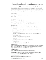
When the web page opens, the Firestar i401 laser begins sending status data based on the laser’s current
condition. Once the initial data is loaded, the
Get Data
button becomes active. Click this button to begin
updating the static web page once a second. Click the
Pause
button to halt updating. If a fault should occur
while the web page is active, the updating process will automatically halt and an error message is displayed.
Displayed data values are accurate to within ±0.25 units.
Get Data button
Click to begin refreshing web page data once a second.
Pause button
Click to halt web page updates.
Laser Status
Displays the current state of laser
Status
indicators.
Note:
Because the i401 web page is a static web page, the RDY indicator display will not flash an error
code; however, the gray
Error messages
section will display the fault.
RF module data
This section displays operating conditions for each of the Firestar i401’s four RF modules.
Connected
A green indicator means that the RF module is connected to the control board. The indicator
changes to red if there is no connection.
Input Voltage (VDC)
Displays the DC voltage level measured at the input of the power board for each RF module.
Switch Voltage (VDC)
Displays the DC voltage level applied to each RF module.
Current (A)
Displays DC current (Amperage) being drawn by each RF module.
Temperature (°C)
Displays the heat sink temperature of each RF module.
Relative Humidity:
Displays the measured relative humidity (R.H.) within the i401 laser housing. When purge gas is flowing,
the R.H. value should drop to 0% (± 10%) within 10–15 minutes. If the relative humidity never drops
below approximately 10%, then increase the purge gas flow rate slightly.
Flow Sensor Temp*:
Displays cooling system temperature measured
after the RF amplifier modules.
Important Note:
The
Flow Sensor Temp
value is
not a measurement of coolant temperature and
should not be used to adjust the chiller’s setpoint!
Internal Tickle Setting:
Indicates that tickle is active and displays the actual tickle setting.
Содержание Firestar i401 Series
Страница 2: ......
Страница 4: ......
Страница 56: ...operation 210 Synrad Firestar i401 operator s manual This page intentionally left blank ...
Страница 112: ...maintenance troubleshooting 422 Synrad Firestar i401 operator s manual This page intentionally left blank ...
Страница 120: ...index i8 Synrad Firestar i401 operator s manual ...

