


technical reference
3
10
Synrad
Firestar i401
operator’s manual
User I/O connections
The
User I/O connections
section includes subsections:
■
User I/O connection summary
■
Input/output signals
■
Sample I/O circuits
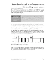
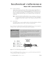
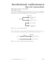
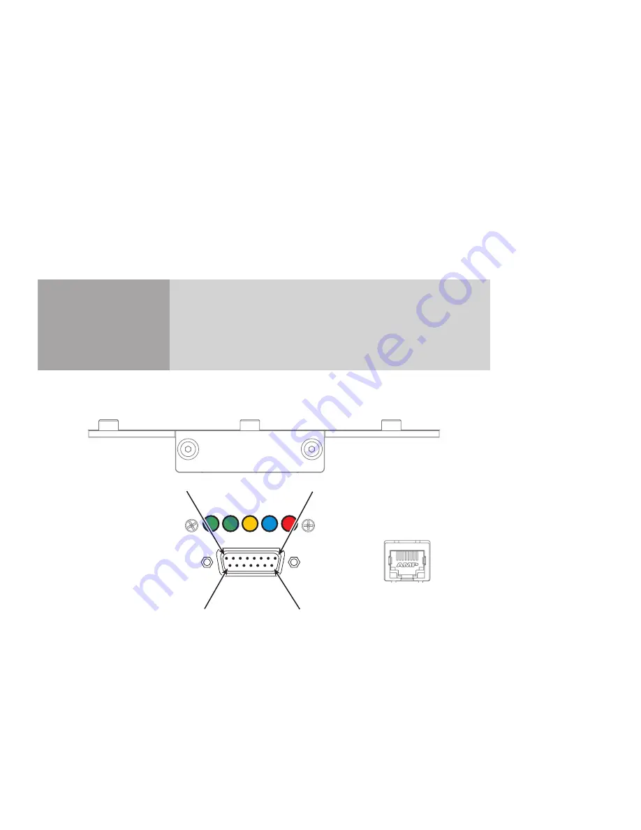
The PWM Command signal and all input/output (I/O) control signals are connected to the
User I/O
port,
a 15 pin female D-type subminiature connector, on the i401’s rear panel. Figure 3-5 below illustrates the
pin arrangement of the
User I/O
connector.
Caution
possible
equipment
damage
Turn off DC power before installing or removing any plug or cable
from the
User I/O
connector. Ensure that user connections are made
to the appropriate pins and that the appropriate signal levels are ap-
plied. Failure to do so may damage the laser.
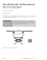
Pin 9
Pin 15
Pin 8
Pin 1
INT
TMP
RDY
USER I/O
ETHERNET
SHT LASE
Figure 3-5
User I/O connector pinouts
Содержание Firestar i401 Series
Страница 2: ......
Страница 4: ......
Страница 56: ...operation 210 Synrad Firestar i401 operator s manual This page intentionally left blank ...
Страница 112: ...maintenance troubleshooting 422 Synrad Firestar i401 operator s manual This page intentionally left blank ...
Страница 120: ...index i8 Synrad Firestar i401 operator s manual ...


