maintenance/
troubleshooting
4
10
Synrad
Firestar i401
operator’s manual
Troubleshooting
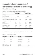
Table 4-3
Effect of Remote Interlock input on operating parameters
Parameter
Remote Interlock Input
Remote Interlock input
Inactive (No V+)
Active (V+ Applied)
INT
LED
Red
Green
Interlock Open
output
Closed
Open
RDY
LED (if
TMP
LED Green)
Off
Off
Yellow Yellow
Laser Ready
output (if
FD
output Open) Open
Open
Closed Closed
Shutter Open Request
input
Inactive
Active
Inactive
Active
SHT
LED
Off
Off
Off
Blue
Shutter Open
output
Open
Open
Open
Closed
Physical shutter position
Closed
Closed
Closed
Open
DC power to RF boards
Off
Off
On
On
Signal input to RF boards
None
None
Tickle
PWM
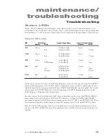
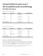
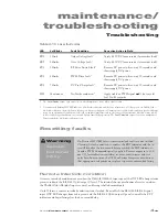
Tables 4-4 through 4-9 show how the Firestar i401’s LED and output signal status changes as various oper-
ating and fault conditions occur. Fault conditions are shown in bold.
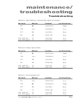
Table 4-4
Normal operating condition
LED Indicator
LED Status
Signal Name
User I/O Signal Status
INT
Green
Interlock Open
Open
TMP
Green
Fault Detected
Open
RDY
Yellow
Laser Ready
Closed
SHT
Blue
Shutter Open
Closed
LASE
(Tickle only)
Off
Laser Active
Open
LASE
(PWM applied)
Red
Laser Active
Closed
Содержание Firestar i401 Series
Страница 2: ......
Страница 4: ......
Страница 56: ...operation 210 Synrad Firestar i401 operator s manual This page intentionally left blank ...
Страница 112: ...maintenance troubleshooting 422 Synrad Firestar i401 operator s manual This page intentionally left blank ...
Страница 120: ...index i8 Synrad Firestar i401 operator s manual ...

