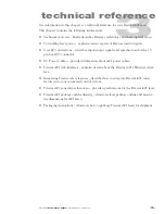


technical reference
3
12
Synrad
Firestar i401
operator’s manual
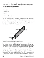
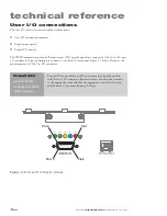
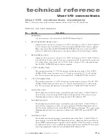
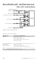
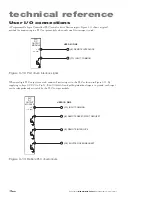
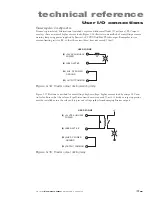
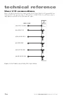
User I/O connections
Pin Function
Description
9
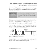
PWM Input
Connect your PWM Command signal (+5 VDC, 5 kHz nominal, 100 kHz max, pulse width
modulated) to this input pin to control laser output power. Refer back to
Controlling laser
power
for further information on laser control signals.
10
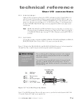
Shutter Open Request input
Apply a positive or negative voltage (±5–24 VDC) with respect to Pin 11,
Input Common
,
to open the internal electromechanical shutter assembly. If your system does not supply a
Shutter Open Request
signal, this pin must be connected to a voltage source in the range
of ±5–24 VDC. Refer to Figure 3-7 for a diagram showing how the
Shutter Open Request
input is factory-jumpered. The shutter will
not activate until a voltage is also applied to the
Remote Interlock
input (
INT
LED illuminated green and
RDY
LED On).
11
Input Common
Use this input pin to connect return lines for
Remote Interlock
,
Shutter Open Request
,
and
Remote Reset/Start Request
lines.
12
Auxiliary DC Power Ground
This connection provides a ground (earth) connection for +5 and +24 VDC auxiliary
power outputs. This pin is the only
User I/O
pin that is connected to chassis ground. Do not
use this pin for grounding if DC power to external I/O circuits is supplied from an external
customer-supplied DC power source.
13
Output Common
Use this pin to complete the return path for output connections (Pin 6, 7, 8, 14, or 15).
The
Output Common
line is protected by a 0.3 A self-resetting fuse.
14
Shutter Open output
This bi-directional switched output is internally connected to Pin 13,
Output Common
,
when
Remote Interlock
and
Shutter Open Request
signals are present (
RDY
indicator
illuminated yellow and
SHT
indicator blue) to indicate that the shutter is open and lasing
is enabled This output is open (high impedance) when the laser is disabled (
SHT
indicator
Off).
15
Interlock Open output
This bi-directional switched output is internally connected to Pin 13,
Output Common
,
when remote interlock circuitry is open (
INT
indicator illuminated red), indicating that
lasing is disabled. The output is open (high impedance) when lasing is enabled (
INT
indi-
cator green).
Содержание Firestar i401 Series
Страница 2: ......
Страница 4: ......
Страница 56: ...operation 210 Synrad Firestar i401 operator s manual This page intentionally left blank ...
Страница 112: ...maintenance troubleshooting 422 Synrad Firestar i401 operator s manual This page intentionally left blank ...
Страница 120: ...index i8 Synrad Firestar i401 operator s manual ...


