63
We reserve the right to make changes without any prior notice.
Translation from original instructions
7.3.3.1
Editing the operating pressure difference in the unit
The procedure below explains how to edit the factory value.
- go to the main screen and press the arrow right button;
-
click the arrow down button to select the “Flowzer” function and then press “Enter” to confirm;
-
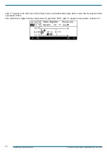
Press the button “SET” to access the screen where the setpoint difference value is set up: use the “arrow” buttons to
move and select the parameter to be edited.
-
Press “ENTER” to enable the edit window.
-
Use the “arrow” buttons to set the new value and press “ENTER” to confirm.
7.3.4 Flowzer VD
The “VD” function is used to set the speed of the pump to keep constant the pressure difference between the delivery and
return lines in the system.
If the pressure difference is kept constant at the ends of the system, the speed of the pump is set automatically in such way
that the desired flow rate is preserved as the load varies.
If the demand from the system is reduced, the pressure difference increases and the controller offsets it by reducing the
pump speed, which results in energy consumption saving.
The controller in units featuring a heat pump offers the possibility to set a pressure difference for operation in cooling mode
and a pressure difference for operation in heating mode, which helps the unit adapt to seasonal requirements.
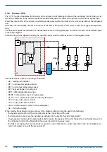
This function requires the installation of pressure probes on the system delivery and return lines.
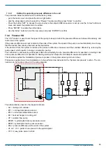
Probes are supplied in a kit and installation is to be performed as instructed in the “System components” section. The con
-
nection is to be made as shown in the wiring diagram.
Vmin.
U2
U1
Un
Y2V
Y2V
Y3V
VP
A2
UL
ΔPp
BPWO
BPWI
UE
BT2
BT1
The abbreviations present in the diagram indicate:
- A2 = cooling unit controller
- BT1 = unit input temperature sensor
- BT2 = unit output temperature sensor
- EU = heat exchanger in cooling unit
-
VP = variable flow pump
-
BPWO = system/plant delivery pressure sensor
-
BPWI = system/plant return pressure sensor
-
ΔPp = pressure difference at the ends of the system
-
U1, U2 .. Un = points of use present in the system/plant
- Y2V = 2-way valve servo controls


