64
We reserve the right to make changes without any prior notice.
Translation from original instructions
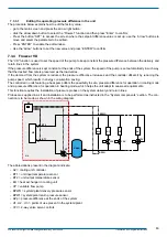
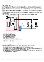
- Y3V = 3-way valve servo controls
-
Vmin = minimum water volume in the system/plant
- UL = limit of the supply.
This type of system requires that the min. water flow rate is also guaranteed when there is no load. This is made possible
through the installation of 3-way valves on the user points.
The installation of 3-way valves on the furthest user points also provides for greater thermal flywheel, which enables limiting
the capacity of the buffer tank.
7.3.4.1
Editing the operating pressure difference in the unit
The procedure below explains how to edit the factory value.
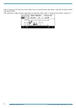
- go to the main screen and press the arrow right button;
-
click the arrow down button to select the “Flowzer” function and then press “Enter” to confirm;
-
Press the button “SET” to access the screen where the setpoint difference value is set up: use the “arrow” buttons to
move and select the parameter to be edited.
-
Press “ENTER” to enable the edit window.
-
Use the “arrow” buttons to set the new value and press “ENTER” to confirm.
Check that the flow rate through the heat exchanger in the unit, including without thermal load, is within the
operating limits admitted in the technical catalogue.
7.3.4.2
Checking of system flow rate
After entering the setpoint difference, we recommend checking that the pump is sized correctly.
Check that the pump can fulfil the max. system demand as follows: open all the user points and check that the speed of the
pump is such as to achieve the stored setpoint difference.
If the setpoint difference fails to be achieved, a new pump must be selected.
Close all the user points in the system and check that the water flow rate through the unit falls within the limits admitted in
the technical catalogue.
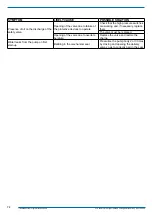
If this condition is not met, replace the 2-way valves in the system with 3-way valves until the min. flow rate is achieved.


