13
We reserve the right to make changes without any prior notice.
Translation from original instructions
2.2.4 Installing the flow switch
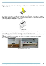
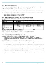
The units are equipped between the evaporator inlet and outlet with a differential pressure switch. A flow switch, that must
be connected by the installer, can be supplied as accessory.
The installed flow switch is provided with a 1” male connector.
The unit must be installed following the arrow that shows the direction of flow.
The installation must be done in a straight section of pipe away from filters, valves, etc. at a distance of at least 5 times the
pipe diameter, both upline and downline.
The flow switch is factory calibrated for installation on a horizontal pipe.
The push rod must be in the vertical position.
The connections of the flow switch with the terminal board in the electrical control panel must be made using the common
terminal and the terminal that is normally open when there is no water circulation.
Check the terminals provided for the flow switch in the wiring diagram of the unit.
Use a 2 x 1 mm² cable or at most a 2 x 1.5 mm² cable, with diameter between 6 and 9 mm, suitable for installation.
Lock the cable in place with cable ties in the section between the flow switch and the inlet to the electrical control panel.
Refer to the instructions provided with the flow switch to identify the correct set of foils.
Correct flow switch/sensor operation requires that the speed of the fluid flowing through them is within the
specified operating limits.
The table below shows the pipe diameters to be used in the system section where the flow switch is to be installed, accor
-
ding to the flow rate.
Hydraulic diameter
Min. flow rate
Max. flow rate
(inches)
m
3
/h
m
3
/h
1"
2,5
3,6
1" 1/4
3,6
6,1
1" 1/2
6,1
9,2
2"
9,2
15,0
2" 1/2
15,0
24,0
3"
24,0
36,0
4"
36,0
60,0
5"
60,0
94,0
6"
94,0
120,0
8"
120,0
240,0
10"
240,0
381,6
Connect the flow switch to the outlet of the user-side heat exchanger indicated in the dimensional diagram.
The Manufacturer declines any and all responsibility for malfunctions due to non-complying installation of the
flow switch.
2.2.5 Unit operating in heat pump mode
The performance of units in heat pump operation goes down as the external air temperature falls.
The units can be equipped with anti-freeze heater for heating the exchanger.
This heater starts working with the unit off, when the temperature of the water leaving the evaporator drops below the an
-
ti-freeze calibration temperature.


