


9-20 ELECTRICAL SYSTEM
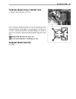
INSPECTION
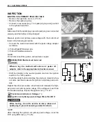
IGNITION COIL PRIMARY PEAK VOLTAGE
• Remove the right side cover. (
$
8-10)
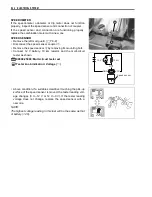
• Remove the spark plug cap.
• Connect a new spark plug
1
to spark plug cap and ground it
to the cylinder head bolt.
NOTE:
Make sure that the spark plug cap and spark plug are connected
properly and the battery is fully-charged.
Measure ignition coil primary peak voltage with the multi-circuit
tester in the following procedure.
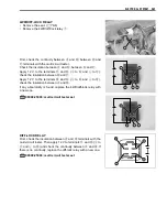
• Connect the multi-circuit tester with the peak voltage adaptor
as follows.
+
Probe: Black/White lead wire
-
Probe: White/Blue lead wire
NOTE:
Do not disconnect the ignition coil lead wire coupler.
%
09900-25008: Multi-circuit tester set
#
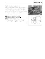
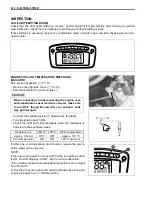
• Shift the transfer to the neutral position and turn the ignition
switch to the “ON” position.
• Push the starter button and allow the engine to crank for a few
seconds, and then measure the ignition coil primary peak volt-
age.
Repeat the above procedure a few times and measure the high-
est ignition coil primary peak voltage. If the voltage is lower than
the standard values, inspect the ignition coil. (
$
9-21)
3
Tester knob indication: Voltage (
4
)
&
Ignition coil primary peak voltage: More than 80 V
!
NOTE:
After checking the ignition coil primary peak voltage, clear the
DTC using SDS tool. (
$
5-23)
When us ing the multi-circuit t ester an d peak v olt
adaptor, refer to the appropriate instruction manual.
While testing, do n ot to uch th e te ster p robes an d
spark plug to prevent receiving an electric shock.
ECM
B/W
W/B
Peak volt adaptor
New
spark
plug
Battery
Содержание LT-A450X
Страница 2: ...SUPPLEMENTS LT A450XK9 09 MODEL LT A450XK8 12 13 WIRING DIAGRAM 14 ...
Страница 47: ...PERIODIC MAINTENANCE 2 29 ...
Страница 48: ...2 30 PERIODIC MAINTENANCE ...
Страница 63: ...ENGINE 3 7 Remove the engine mounting nuts Remove the engine from the right side ...
Страница 215: ......
Страница 315: ...7 24 COOLING AND LUBRICATION SYSTEM ENGINE LUBRICATION SYSTEM To cylinder head OIL PUMP ...
Страница 316: ...COOLING AND LUBRICATION SYSTEM 7 25 EXHAUST SIDE INTAKE SIDE ...
Страница 317: ......
Страница 321: ...CHASSIS 8 3 1 Rear fender 4 Left upper mud guard 2 Right mud guard 5 Rear box 3 Left lower mud guard ...
Страница 332: ...8 14 CHASSIS REAR CARRIER Remove the rear carrier REAR BOX Remove the rear box 1 ...
Страница 335: ...CHASSIS 8 17 Apply a small quantity of THREAD LOCK 1342 to the rear carrier mounting bolts 99000 32050 THREAD LOCK 1342 ...
Страница 417: ......
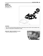
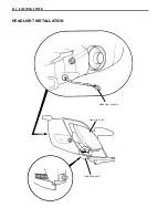
Страница 452: ...9 34 ELECTRICAL SYSTEM HEADLIGHT INSTALLATION Head light coupler Head light R Adjusting point ...
Страница 483: ...SERVICING INFORMATION 10 25 FENDER INSTALLATION Front fender Right inner fender Left mud guard Left inner fender ...
Страница 484: ...10 26 SERVICING INFORMATION Rear box Rear fender Right mud guard Left mud guard ...
Страница 510: ......
Страница 514: ......


