8-20 CHASSIS
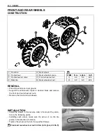
• When installing each tire, make sure the arrow
A
on the tire
points in the direction of rotation. Also, make sure the outer
side of the wheel rim is facing outward.
NOTE:
For inspecting the tires, refer to page 2-26.
Inspect the valve cores, before installing.
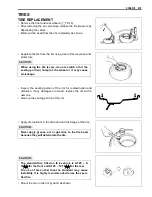
• Inflate the tire to seat the tire bead.
&
Maximum tire bead seat pressure
Front : 250 kPa (2.5 kgf/cm², 36 psi)
Rear : 250 kPa (2.5 kgf/cm², 36 psi)
#
NOTE:
Check the “rim line”
1
cast on the tire sidewalls. It must be equi-
distant from the wheel rim all the way around. If the distance
between the rim line and the wheel rim varies, this indicates that
the bead is not properly seated. If this is so, deflate the tire com-
pletely, and unseat the tire bead on both sides. Then, coat the
bead with clean water, and re-seat the tire.
• Adjust the tire pressure to the specified pressure.
&
Cold inflation tire pressure
Front : 35 kPa (0.35 kgf/cm
2
, 5.1 psi)
Rear : 30 kPa (0.30 kgf/cm
2
, 4.4 psi)
&
Vehicle load capacity: 172 kg (380 lbs)
#
&
Maximum operating pressure
✩
: 25 kPa (0.25 kgf/cm
2
, 3.6 psi)
✩✩
: 35 kPa (0.35 kgf/cm
2
, 5.1 psi)
✩✩✩
: 45 kPa (0.45 kgf/cm
2
, 6.5 psi)
Place th e t ire under a pr otective tire cag e or si milar
protective covering device before inflating the tire. To
minimize the possibility of tire damage when seating
the tire bead, never exceed the MAXIMUM TIRE BEAD
SEAT PRESSURE rating shown on the tire.
Before in flating th e tire , c heck the M AXIMUM OPE R-
ATING PRESSURE rating of the tire. This is indicated
by a “
✩
” following the tire size shown on the sidewall.
The number of “
✩
” on the tire indicates the maximum
operating pressure.
Содержание LT-A450X
Страница 2: ...SUPPLEMENTS LT A450XK9 09 MODEL LT A450XK8 12 13 WIRING DIAGRAM 14 ...
Страница 47: ...PERIODIC MAINTENANCE 2 29 ...
Страница 48: ...2 30 PERIODIC MAINTENANCE ...
Страница 63: ...ENGINE 3 7 Remove the engine mounting nuts Remove the engine from the right side ...
Страница 215: ......
Страница 315: ...7 24 COOLING AND LUBRICATION SYSTEM ENGINE LUBRICATION SYSTEM To cylinder head OIL PUMP ...
Страница 316: ...COOLING AND LUBRICATION SYSTEM 7 25 EXHAUST SIDE INTAKE SIDE ...
Страница 317: ......
Страница 321: ...CHASSIS 8 3 1 Rear fender 4 Left upper mud guard 2 Right mud guard 5 Rear box 3 Left lower mud guard ...
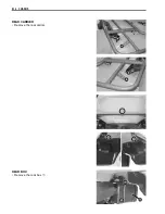
Страница 332: ...8 14 CHASSIS REAR CARRIER Remove the rear carrier REAR BOX Remove the rear box 1 ...
Страница 335: ...CHASSIS 8 17 Apply a small quantity of THREAD LOCK 1342 to the rear carrier mounting bolts 99000 32050 THREAD LOCK 1342 ...
Страница 417: ......
Страница 452: ...9 34 ELECTRICAL SYSTEM HEADLIGHT INSTALLATION Head light coupler Head light R Adjusting point ...
Страница 483: ...SERVICING INFORMATION 10 25 FENDER INSTALLATION Front fender Right inner fender Left mud guard Left inner fender ...
Страница 484: ...10 26 SERVICING INFORMATION Rear box Rear fender Right mud guard Left mud guard ...
Страница 510: ......
Страница 514: ......

