3-76 ENGINE
FINAL ASSEMBLY
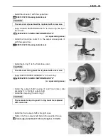
• After adjusting the gear backlash and tooth contact correctly,
remove the output shaft and rear output shaft drive bevel
gear.
• Clean off any machinist’s dye or paste from the gear teeth,
and lubricate the teeth with engine oil.
• Tighten the output shaft nut and drive bevel gear nut to the
specified torque.
"
Output shaft nut: 100 N·m (10.0 kgf-m, 72.5 lb-ft)
Drive bevel gear nut: 100 N·m (10.0 kgf-m, 72.5 lb-ft)
%
09920-53740: Clutch sleeve hub holder
• Stake the collar of the nut into the notch in the shaft.
Part No.
Shim thickness
24935-03G50-068
0.550 mm (0.0217 in)
0.575 mm (0.0226 in)
0.600 mm (0.0236 in)
0.625 mm (0.0246 in)
0.650 mm (0.0256 in)
0.675 mm (0.0266 in)
24935-03G50-065
24935-03G50-063
24935-03G50-060
24935-03G50-058
24935-03G50-055
24935-03G50-083
0.700 mm (0.0276 in)
0.725 mm (0.0285 in)
0.750 mm (0.0295 in)
0.775 mm (0.0305 in)
0.800 mm (0.0315 in)
0.825 mm (0.0325 in)
24935-03G50-080
24935-03G50-078
24935-03G50-075
24935-03G50-073
24935-03G50-070
24935-03G50-098
0.850 mm (0.0335 in)
0.875 mm (0.0344 in)
0.900 mm (0.0354 in)
0.925 mm (0.0364 in)
0.950 mm (0.0374 in)
0.975 mm (0.0384 in)
24935-03G50-095
24935-03G50-093
24935-03G50-090
24935-03G50-088
24935-03G50-085
24935-03G50-113
1.000 mm (0.0394 in)
1.025 mm (0.0404 in)
1.050 mm (0.0413 in)
1.075 mm (0.0423 in)
1.100 mm (0.0433 in)
1.125 mm (0.0443 in)
24935-03G50-110
24935-03G50-108
24935-03G50-105
24935-03G50-103
24935-03G50-100
24935-03G50-115
1.150 mm (0.0453 in)
24935-03G50-130
1.175 mm (0.0463 in)
1.200 mm (0.0472 in)
1.225 mm (0.0482 in)
1.250 mm (0.0492 in)
1.275 mm (0.0502 in)
1.300 mm (0.0512 in)
24935-03G50-128
24935-03G50-125
24935-03G50-123
24935-03G50-120
24935-03G50-118
Содержание LT-A450X
Страница 2: ...SUPPLEMENTS LT A450XK9 09 MODEL LT A450XK8 12 13 WIRING DIAGRAM 14 ...
Страница 47: ...PERIODIC MAINTENANCE 2 29 ...
Страница 48: ...2 30 PERIODIC MAINTENANCE ...
Страница 63: ...ENGINE 3 7 Remove the engine mounting nuts Remove the engine from the right side ...
Страница 215: ......
Страница 315: ...7 24 COOLING AND LUBRICATION SYSTEM ENGINE LUBRICATION SYSTEM To cylinder head OIL PUMP ...
Страница 316: ...COOLING AND LUBRICATION SYSTEM 7 25 EXHAUST SIDE INTAKE SIDE ...
Страница 317: ......
Страница 321: ...CHASSIS 8 3 1 Rear fender 4 Left upper mud guard 2 Right mud guard 5 Rear box 3 Left lower mud guard ...
Страница 332: ...8 14 CHASSIS REAR CARRIER Remove the rear carrier REAR BOX Remove the rear box 1 ...
Страница 335: ...CHASSIS 8 17 Apply a small quantity of THREAD LOCK 1342 to the rear carrier mounting bolts 99000 32050 THREAD LOCK 1342 ...
Страница 417: ......
Страница 452: ...9 34 ELECTRICAL SYSTEM HEADLIGHT INSTALLATION Head light coupler Head light R Adjusting point ...
Страница 483: ...SERVICING INFORMATION 10 25 FENDER INSTALLATION Front fender Right inner fender Left mud guard Left inner fender ...
Страница 484: ...10 26 SERVICING INFORMATION Rear box Rear fender Right mud guard Left mud guard ...
Страница 510: ......
Страница 514: ......


