DRIVE TRAIN 4-17
REMOUNTING
Remount the front drive train (differential) gear case assembly in
the reverse order of removal. Pay attention to the following
points:
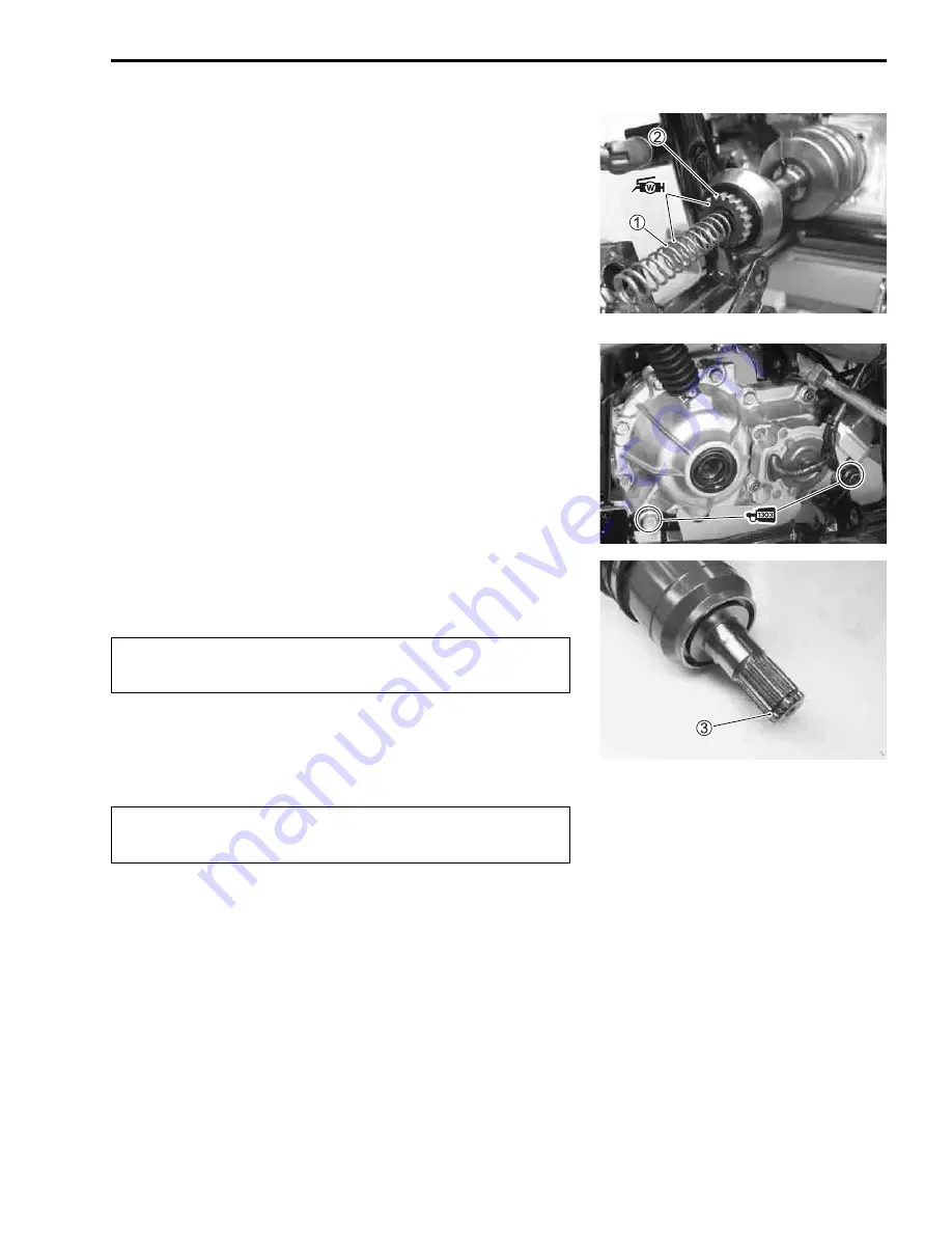
• Install the front propeller shaft spring
1
.
• Apply a small quantity of WATER RESISTANCE GREASE to
the front propeller shaft spring
1
and spline of the front pro-
peller shaft
2
.
1
99000-25160: WATER RESISTANCE GREASE
• Apply a small quantity of THREAD LOCK SUPER “1303” to
the front drive train (differential) gear case mounting nuts.
*
99000-32030: THREAD LOCK SUPER “1303”
• Tighten the front drive train (differential) gear case mounting
nuts to the specified torque.
"
Front drive train (diffrential) gear case mounting bolt/nut:
50 N·m (5.0 kgf-m, 36.0 lb-ft)
• Install the stopper ring
3
into the groove of front drive shaft
spline.
#
• Apply SUZUKI SUPER GREASE “A” to the spline.
,
99000-25010: SUZUKI SUPER GREASE “A”
(or equivalent grease)
#
NOTE:
After installing both drive shafts, make sure the stopper rings are
seated properly by pulling both inboard joints lightly.
• Pour the specified hypoid gear oil (SAE #90) through the filler
hole. (
$
2-11)
&
Front differential gear oil capacity:
500 ml (16.9 US oz, 17.6 Imp oz)
• Install the front suspension. (
$
8-47)
• Install the front brake caliper. (
$
8-33)
• Install the front wheels. (
$
8-18)
The rem oved st opper ring m ust be re placed with a
new one.
Be careful not to damage the front drive train (differen-
tial) gear case oil seals.
Содержание LT-A450X
Страница 2: ...SUPPLEMENTS LT A450XK9 09 MODEL LT A450XK8 12 13 WIRING DIAGRAM 14 ...
Страница 47: ...PERIODIC MAINTENANCE 2 29 ...
Страница 48: ...2 30 PERIODIC MAINTENANCE ...
Страница 63: ...ENGINE 3 7 Remove the engine mounting nuts Remove the engine from the right side ...
Страница 215: ......
Страница 315: ...7 24 COOLING AND LUBRICATION SYSTEM ENGINE LUBRICATION SYSTEM To cylinder head OIL PUMP ...
Страница 316: ...COOLING AND LUBRICATION SYSTEM 7 25 EXHAUST SIDE INTAKE SIDE ...
Страница 317: ......
Страница 321: ...CHASSIS 8 3 1 Rear fender 4 Left upper mud guard 2 Right mud guard 5 Rear box 3 Left lower mud guard ...
Страница 332: ...8 14 CHASSIS REAR CARRIER Remove the rear carrier REAR BOX Remove the rear box 1 ...
Страница 335: ...CHASSIS 8 17 Apply a small quantity of THREAD LOCK 1342 to the rear carrier mounting bolts 99000 32050 THREAD LOCK 1342 ...
Страница 417: ......
Страница 452: ...9 34 ELECTRICAL SYSTEM HEADLIGHT INSTALLATION Head light coupler Head light R Adjusting point ...
Страница 483: ...SERVICING INFORMATION 10 25 FENDER INSTALLATION Front fender Right inner fender Left mud guard Left inner fender ...
Страница 484: ...10 26 SERVICING INFORMATION Rear box Rear fender Right mud guard Left mud guard ...
Страница 510: ......
Страница 514: ......


