


NICE3000
new
User Manual Mechanical and Electrical Installation
- 59 -
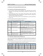
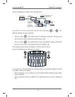
3.6 Selection of Peripheral Electrical Devices
3.6.1 Description of Peripheral Electrical Devices
1. Do not install the capacitor or surge suppressor on the output side of the controller.
Otherwise, it may cause faults to the controller or damage to the capacitor and surge
suppressor.
2. Inputs/Outputs (main circuit) of the controller contain harmonics, which may interfere
with the communication device connected to the controller. Therefore, install an anti-
interference filter to minimize the interference.
3. Select the peripheral devices based on actual applications as well as by referring to
section 3.6.2.
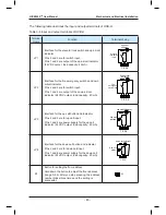
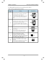
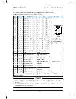
The following table describes the peripheral electrical devices.
Table 3-14 Description of peripheral electrical devices
Part
Mounting Location
Function Description
MCCB
Forefront of controller
power input side
Cut off the power supply of the controller and
provide short-circuit protection.
Safety
contactor
Between MCCB and the
controller input side
Apply/Cut off the power supply of the controller.
The close/open of the contactor is controlled by the
external safety circuit.
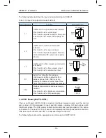
AC input
reactor
Controller input side
Improve the power factor of the input side.
Eliminate the higher harmonics on the input side to
provide effective protection on the rectifier bridge.
Eliminate the input current unbalance due to
unbalance between the power phases.
AC
output
reactor
Between the controller
output side and the motor,
close to the controller
If the distance between the controller and the
motor is greater than 100 m, install an AC output
reactor.
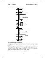
3.6.1 Selection of Peripheral Electrical Devices
Proper cable specification and cabling greatly improves anti-interference capability and
safety of the system, facilitating installation and commissioning and enhancing system
running stability.
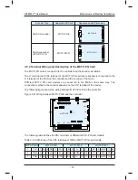
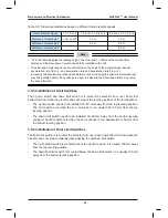
The following table describes the specifications of peripheral electrical devices for selection.
Table 3-15 Specification of peripheral electrical devices for selection
Controller
Model
MCCB (A) Contactor
(A)
Cable of Main
Circuit (mm²)
Cable of Control
Circuit (mm²)
Grounding
Cable (mm²)
NICE-2002
16
18
2.5
0.75
2.5
NICE-2003
25
25
2.5
0.75
2.5
NICE-4002
10
12
2.5
0.75
2.5
Содержание NICE3000 New
Страница 1: ......
Страница 13: ......
Страница 14: ...1 Safety Information and Precautions ...
Страница 21: ...Safety Information and Precautions NICE3000new User Manual 20 ...
Страница 22: ...2 Product Information ...
Страница 33: ...Product Information NICE3000new User Manual 32 ...
Страница 34: ...3 Mechanical and Electrical Installation ...
Страница 67: ...4 Use of the NICE3000new ...
Страница 79: ...5 System Commissioning and Application Example ...
Страница 105: ...6 Function Code Table ...
Страница 136: ...Function Code Table NICE3000new User Manual 134 ...
Страница 137: ...7 Description of Function Codes ...
Страница 205: ...8 EMC ...
Страница 214: ...EMC NICE3000new User Manual 212 ...
Страница 215: ...9 Troubleshooting ...
Страница 230: ......
Страница 233: ......