


NICE3000
new
User Manual Description of Function Codes
- 155 -
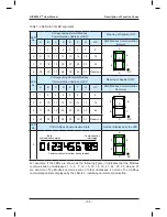
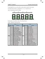
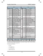
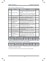
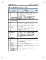
Table 7-2 Definition of LED segments
LED
No.
Corresponding Normal Modbus
Communication Address of LED
Meaning of Segment ON
A
B
C
D
E
F
G
DP
HOP Modbus Communication
Normal
1
1
2
3
4
5
6
7
8
A
B
C
DP
D
E
F
G
2
9
10
11
12
13
14
15
16
3
17
18
19
20
21
22
23
24
4
25
26
27
28
29
30
31
Reserved
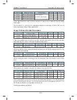
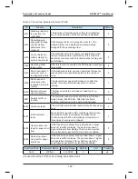
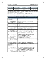
LED
No.
Corresponding Abnormal Modbus
Communication Address of LED
Meaning of Segment OFF
A
B
C
D
E
F
G
DP
HOP Modbus Communication
Abnormal
1
1
2
3
4
5
6
7
8
A
B
C
DP
D
E
F
G
2
9
10
11
12
13
14
15
16
3
17
18
19
20
21
22
23
24
4
25
26
27
28
29
30
31
Reserved
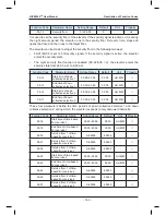
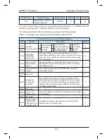
LED
No.
CTB CANbus Communication State
Number Displayed by the LED
5
Communication status from strong to weak
Best
communication status
Communication
interrupted
A
B
C
DP
D
E
F
G
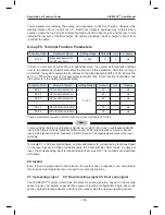
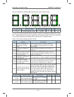
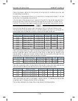
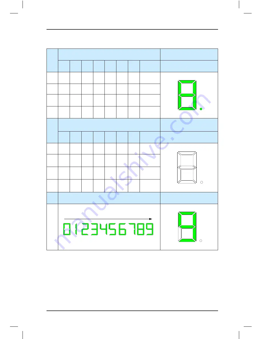
For example, if the LEDs are shown as the following figure, it indicates that the Modbus
communication of addresses 1, 5, 6, 7, 12, 15, 16, 18, 19, 21, 22, 23, 25, 26 and 27
are abnormal. The Modbus communication of other addresses is normal. The CANbus
communication state displayed by the LED is 3, indicating normal communication.
Содержание NICE3000 New
Страница 1: ......
Страница 13: ......
Страница 14: ...1 Safety Information and Precautions ...
Страница 21: ...Safety Information and Precautions NICE3000new User Manual 20 ...
Страница 22: ...2 Product Information ...
Страница 33: ...Product Information NICE3000new User Manual 32 ...
Страница 34: ...3 Mechanical and Electrical Installation ...
Страница 67: ...4 Use of the NICE3000new ...
Страница 79: ...5 System Commissioning and Application Example ...
Страница 105: ...6 Function Code Table ...
Страница 136: ...Function Code Table NICE3000new User Manual 134 ...
Страница 137: ...7 Description of Function Codes ...
Страница 205: ...8 EMC ...
Страница 214: ...EMC NICE3000new User Manual 212 ...
Страница 215: ...9 Troubleshooting ...
Страница 230: ......
Страница 233: ......