


Chapter 6: Advanced Chassis Setup
6-3
6-2 Control Panel
The front control panel must be connected to the JF1 connector on the serverboard
to provide you with system status and alarm indications. A ribbon cable has bundled
these wires together to simplify this connection. Connect the cable from JF1 on
the serverboard (making sure the red wire plugs into pin 1) to the appropriate
comnnector on the front control panel PCB (printed circuit board). Pull all excess
cabling over to the control panel side of the chassis. The LEDs on the control
panel inform you of system status – see Figure 6-2 for details. See Chapter 5 for
details on JF1.
6-3 System Fans
Three 9-cm chassis cooling fans (located in the center of the chassis) provide
cooling airflow while three 8-cm exhaust fans expel hot air from the chassis. The
fans should all be connected to headers on the serverboard (see Chapter 5). Each
power supply module also has a cooling fan.
Fan Failure
Under normal operation all chassis fans, exhaust fans and the power supply fans
run continuously. The chassis fans are hot-swappable and can be replaced without
powering down the system.
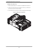
Replacing Chassis Fans
Identifying the Failed Fan.
1. To locate and replace a failed chassis fan, begin by removing the top/left
chassis cover (see Chapter 2 for details on removing the cover).
2. Locate the fan that has stopped working.
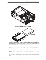
Removing a Hot-plug Fan Housing.
1. Depress the locking tab on the failed fan: on a chassis fan, puch the tab on
the side of the housing inward, on the exhaust fan push down on the colored
tab.
2. With the tab depressed, pull the fan straight out (see Figure 6-3). The wiring
for these fans has been designed to detach automatically.
Содержание A+ SERVER 4042G-6RF
Страница 1: ... SUPER A SERVER 4042G 6RF TRF USER S MANUAL Revision 1 0d ...
Страница 5: ...v Preface Notes ...
Страница 10: ...Notes x A SERVER 4042G 6RF TRF User s Manual ...
Страница 25: ...Chapter 2 Server Installation 2 9 Figure 2 5 Accessing the Inside of the System ...
Страница 30: ...3 4 4042G 6RF TRF User s Manual Notes ...
Страница 50: ...4 20 A SERVER 8027R TRF 7RFT User s Manual Notes ...
Страница 92: ...6 10 A SERVER 4042G 6RF TRF User s Manual Figure 6 7 Removing a Power Supply Module ...
Страница 110: ...A 2 A SERVER 4042G 6RF TRF User s Manual Notes ...


